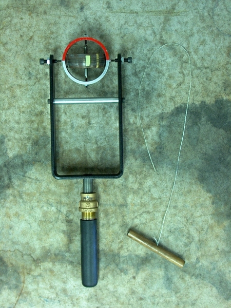
With the gyroscope oriented as shown above, just below the washer at the top of the flywheel shaft is a small hole. Insert the end of the string in the hole, and turn the flywheel to wind the string around the shaft. Holding the hoop (gimbal) steady, give the wooden handle a firm pull to start the flywheel spinning. If you now hold the handle vertical, as long as you hold it still or move it in a straight line in any direction, the gyroscope shows no preferred orientation. If you rotate the handle about its (vertical) axis, or move it in a horizontal arc, the flywheel snaps into a vertical position, so that it is rotating in the same direction in which you turned the handle or moved it in an arc.
Several demonstrations in this section illustrate the behavior of objects that are rotating and thus possess angular momentum, in particular the motion that results when you try to change the object’s angular momentum. For example, when gravity exerts a (horizontal) torque on a spinning top or hanging, spinning bicycle wheel, it precesses. (See demonstrations 28.54 -- Bicycle wheel as a top, and 28.57 -- Bicycle wheel precession.) An instrument whose operation is based on the stability of rotating objects, and the way in which they react to an applied torque, is called a gyroscope.
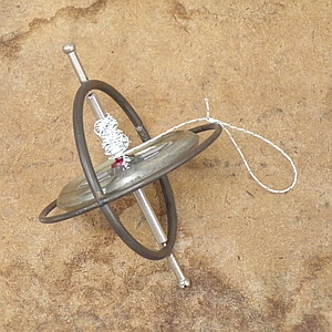
A gyroscope is a spinning disc or flywheel, which can be suspended in various ways. Most toy gyroscopes have a flywheel on a spindle, whose ends sit in a frame. Typically, this frame is a ring that has an extension at either end of the flywheel spindle, in line with its axis, and usually another ring fixed perpendicular to it, encircling the flywheel. At the end of each extension is a ball, which one can set in a depression on a stand. Usually, the ball at the end of one extension has a slot cut in it, by which one can rest the unit on a taught string. Below is a photograph of such a gyroscope.
When the flywheel of the gyroscope is spinning, and you set it on a stand, it precesses as would a spinning top. If you set the spinning gyroscope on a taut string by placing the slotted end on it, the torque exerted by the string prevents the gyroscope from precessing, and it balances on the string, oscillating back and forth. In at least one type of gyroscope used for navigation, the spinning flywheel is mounted in gimbals. The flywheel is mounted inside one ring, which is attached to a larger ring via pivots that are on an axis that is perpendicular to the axis of rotation of the flywheel. This larger ring is similarly attached to an outer ring, via pivots that are on an axis that is perpendicular to the axis along which it is attached to the inner ring. With proper initial orientation of the spinning flywheel, it is thus free to rotate about three mutually perpendicular axes. This arrangement prevents the transmission of any torque from the outermost ring to the flywheel. The gyroscope can thus maintain its orientation no matter how the outermost ring moves, and it provides a directional reference.
The gyroscope in this demonstration has only one gimbal, which is attached to a fork by pivots on a line that is perpendicular to the spin axis of the flywheel that is mounted in it. This means that there is only one axis besides the spin axis, about which the flywheel is free to rotate. If you set the flywheel spinning as described above, as long as you keep the fork still or move it along a straight line, the flywheel does not show a particular preference for a specific orientation. As soon as you either move the fork in an arc or turn it about its central axis, the flywheel snaps to the vertical in the direction in which its angular momentum vector is parallel to the axis about which you rotated the fork. For example, if you set the flywheel spinning in the clockwise direction as viewed from above (in the orientation shown in the photograph), then if you move the fork in an arc to the right or twist the handle in the clockwise direction, the red half of the gimbal snaps to the top. If you then move the fork in an arc to the left or twist the handle in the counterclockwise direction, the gimbal flips so that the red half is on the bottom. If you set the flywheel spinning in the counterclockwise direction, these directions reverse.
To see why this happens, let us say that the flywheel is spinning clockwise; its angular momentum vector, L, points toward the silver side of the gimbal. If we now twist the fork to the right, or move it in an arc to the right, we exert a clockwise torque about the vertical axis of the fork, which imparts a downward change in the angular momentum. If the flywheel were not spinning, it would merely rotate about the fork axis as we rotated the fork; its angular momentum would be due entirely to the torque that we applied. (If it were sitting with its rotation axis vertical, we could apply no torque to the flywheel, since it is free to rotate. In any other orientation, however, the torque we apply would rotate the flywheel about the vertical axis. Actually, any friction in the bearing should introduce a small change in angular momentum when we twist the fork with the axis vertical, and moving the fork in an arc introduces a change in angular momentum in any case.) Since it is spinning, however, and the gimbal is free to rotate about the horizontal axis, it can change the angular momentum in the vertical direction by rotating to align its spin axis with the vertical axis of the fork. The gimbal quickly rotates until the silver half is down (so the red half is up). If we twist the fork or move it in an arc in the opposite direction, the resulting change in angular momentum is in the opposite direction, and the gimbal rotates so that the silver half is up (so the red half is down). Note that initially there is no angular momentum about the horizontal axis. Since the gimbal is free to pivot about this axis, there can be no torque about it, so the angular momentum about it must remain zero. As we rotate the fork about the vertical axis, the flywheel acquires a component of angular momentum along the horizontal axis. When this happens, the gimbal begins to flip about the horizontal axis, which gives rise to angular momentum that cancels this horizontal component of angular momentum. Once the flywheel axis is parallel to the vertical axis of the yoke, it stops rotating about the horizontal axis and stays there.
Of course, as noted above, if the flywheel is spinning in the counterclockwise direction, then moving or twisting the fork as described above results in the gyroscope flipping in opposite directions to those described above. As we might expect, the response of this gyroscope is in the same direction as that of the suitcase in demonstration 28.63 – Rotating wheel in suitcase.
The behavior that this gyroscope exhibits – the flipping of the flywheel so that its spin axis is parallel to the axis about which the gyroscope is rotated – is the basis for the gyrocompass, whose flywheel aligns its spin axis to be parallel to, or in the same plane as, the earth’s axis of rotation, and thus to indicate north.
Analysis of the motion of a gyrocompass
Imagine the apparatus in this demonstration with the hoop oriented in the horizontal plane, and the yoke mounted to a drive that rotates it about the (central) vertical axis at an angular rate of Ω. The flywheel is spinning at a rate of ωs and has an angular momentum along its rotation axis of Ls = Isωs. Since the horizontal axis is on a pivot, the angular momentum along it, Lh is consant, and dLh/dt = 0. There are two ways in which a change in the orientation of the flywheel axis can change Lh. If we call the angle between vertical and the flywheel axis θ, and the moment of inertia of the flywheel about the horizontal axis (the pivot axis of the hoop) I⊥, then Lh = I⊥dθ/dt, and dLh/dt just from the rotation of the flywheel about the horizontal axis is I⊥d2θ/dt2. Lh can also change because of a change in direction of Ls. The horizontal component of Ls = Ls sin θ, and its rate of increase along the horizontal axis is ΩLs sin θ. Adding these together gives
dLh/dt = I⊥d2θ/dt2 + ΩLs sin θ.
As noted above, dLh/dt = 0, and, rearranging the above, we have
d2θ/dt2 + (ΩLs/I⊥) sin θ = 0.
This is similar to the equation for a simple harmonic oscillator (see demonstration 40.12 -- Mass-springs with different spring constants and masses, or demonstration 40.21 -- Pendulums of different lengths and masses).
When the flywheel has rotated to where its axis is close to vertical, sin θ ≈ θ, and the gyroscope undergoes simple harmonic motion:
θ = θ0 sin βt,
where
β = √(ΩLs/I⊥) = √ (ΩIsωs/I⊥)
Once the flywheel axis is almost vertical, it oscillates about the vertical with a frequency ν = β/2π, and a period of T = 2π/β. Eventually, friction in the bearings that support the gyroscope on its horizontal axis damps the motion, and it stops parallel to Ω.
To use such a device as a gyrocompass, we should mount the gimbal that holds the flywheel so that the axis about which it rotates is vertical (like setting the apparatus in this demonstration with the handle horzontal and the fork tines in a vertical plane). The rotation axis of the flywheel then sits horizontal, and can rotate in a horizontal plane.
With the gyroscope oriented this way, Ω is Ωe, the rotation of the earth, and Ωe = 2π rad/day, or 7.272 × 10⁻⁵ rad/s. The component of Ωe that is perpendicular to the the axis about which the gimbal rotates (the component along the vertical axis) is Ωecos λ, where λ is the latitude at which the gyroscope sits. For small oscillations, which occur when the flywheel axis is close to alignment with the northerly direction, the period is
T = 2π/β = 2π√(I⊥/IsωsΩe cos λ)
If we make the rotor a thin disc, I⊥/Is = 1/2. For a gyroscope whose flywheel is rotating at 20,000 rpm (2,094 rad/s), set at the equator, the period of oscillation is 11.4 s. As the latitude angle increases, so does the period of oscillation. Near the north pole, the period becomes too long for the gyroscope to be useful. Note that the period of oscillation goes as the inverse square root of the speed at which the flywheel rotates, and of the speed of rotation of the system.
To use such an instrument on a plane or a ship, one must take special care that it responds only to the rotation of the earth, and not the motion of the plane or ship.
With the apparatus in this demonstration, depending on how fast the flywheel is spinning, and on how you move the yoke, you may observe some oscillation in the orientation of the flywheel axis as it aligns with the axis about which you rotate the apparatus.
References:
1) Kleppner, Daniel and Kolenkow, Robert J. An Introduction to Mechanics (Cambridge, UK: Cambridge University Press, 2010), pp. 301-304.
