
A video of this demonstration is available at this link.
Two signal generators are connected, each to a speaker and to one channel of an oscilloscope, and set to produce a sine wave. The oscilloscope shows a trace for each signal generator. A third trace shows the sum of the two sine waves. (The math function gives the difference between the two channels, but since the input to channel two is inverted, this difference is really the sum.) When you set the signal generators to the same frequency, you and the class hear a pure, steady tone, and the amplitude of the sum remains constant. As you change the frequency of one of the signal generators, you begin to hear beats, and the amplitude of the sum trace on the oscilloscope fluctuates. The beat frequency equals the difference of the frequencies of the two signal generators. The oscilloscope shown in the photograph can be connected to the data projector in the lecture hall.
The idea of this demonstration is to illustrate the beats that occur when one sounds two tones that are close in frequency to each other, but not exactly the same frequency, and also to provide a visual representation of the resulting waveform. As noted above, when you set the signal generators to the same frequency the class hears a pure tone. As you change the frequency of one of the signal generators, the class begins to hear beats, and to see the corresponding fluctuation in the sum trace on the oscilloscope.
What is happening:
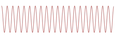
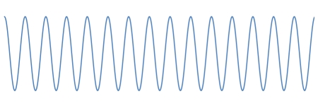
Beats are a phenomenon caused by the superposition of two waves that have slightly different frequencies. These waves can, of course, be of any shape, and they do not have to be the same amplitude, but the case of two sinusoidal waves of equal amplitude makes a good illustration. Below are two sinusoids, the one on top having 20 cycles and the bottom one having 15 cycles. If we take the length of the plots as corresponding to one second, then these represent two waves, one of 20 Hz and one of 15 Hz.
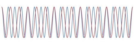
Below, at left are the two waves superimposed on each other. You can see that because of their different frequencies, at some points they are in phase, and at some points they are out of phase. The graph on the right is the sum of the two waves, with dashed lines showing the envelope of the resulting wave. The peaks, of course, correspond to places where the waves are in phase, and the nodes occur where they are out of phase.
→ In the wave on the right, there are now five maxima in the same time span in which there were 20 and 15 in the two original waves. If we call the frequencies of the two individual waves ν1 and ν2, for a particular point we can express the displacements produced by the waves as y1 = A cos 2πν1t and y2 = A cos 2πν2t, respectively (where A = ymax). The superposition of the two waves gives the resultant displacement as y = y1 + y2 = A (cos 2πν1t + cos 2πν2t). Because of the way cosines add, this can be written:
The resulting wave thus has a frequency of (ν1 + ν2)/2, the average of the two individual frequencies, and the amplitude factor is now the quantity in brackets, which varies with a frequency of (ν1 - ν2)/2. A maximum in amplitude occurs whenever cos 2 π((ν1 - ν2)/2)t = 1 or -1. Since each of these values occurs once per cycle, the beat frequency is twice the term in parentheses, or ν1 - ν2, the difference between the frequencies of the two individual waves. Hence the 5-Hz beat in the example above for the sum of a 20-Hz wave and a 15-Hz wave.
If the frequencies of two waves are far apart, their sum merely results in a complex waveform, in which the higher-frequency component “rides on” the lower-frequency one. If the frequencies are close, but both relatively high, the beats can occur at high frequencies. The production of audio-frequency beats from two radio-frequency oscillations is the basis of an electronic instrument called the theremin.
References:
1) Resnick, Robert and Halliday, David. Physics, Part One, Third Edition (New York: John Wiley and Sons, 1977), pp. 419-420, 444-445.
")
