
This is an Eisco model of a four-cycle gasoline engine. It shows the mechanical working parts of a one-cylinder four-cycle gasoline engine, with the crankcase, cylinder, piston, cylinder head and intake and exhaust manifolds in cutaway view. The hand crank is attached to the crankshaft, so that turning it causes the piston to move up and down inside the cylinder. (You must turn it clockwise for the engine to operate properly.) A drive gear at the opposite end of the crankshaft turns a timing gear, which turns a camshaft at the rear of the model, which operates the intake and exhaust valves at the top of the cylinder. A cam attached to the timing gear operates a microswitch so that just before the top of the compression stroke, a bright white LED lights to simulate the firing of the spark plug.
The gasoline engine and the cycle by which it operates are sometimes named after Nikolaus Otto, who in 1876 was the first to make a practical, operating model of a spark-ignition internal combustion engine. The Otto cycle has four steps, which are noted below:
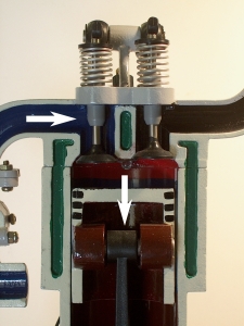
Intake: With the piston at the top of the cylinder, the intake valve (at left) opens. The rotating crankshaft pulls the piston downward, increasing the volume of the cylinder and thus lowering the pressure. This causes fuel-air mixture to be drawn from the intake manifold into the cylinder. |
 |
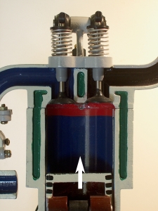
Compression: When the piston has reached the bottom of the intake stroke, the intake valve closes, and the rotating crankshaft forces the piston upward, compressing the fuel-air mixture. This corresponds to the adiabatic compression of the gas inside the cylinder (1). |
 |
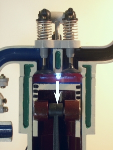
Power: Just before the piston reaches the top of the compression stroke, the spark plug fires, igniting the fuel-air mixture. The increased pressure generated by the expanding gases produced by combustion of the fuel forces the piston downward, turning the crankshaft. The ignition and combustion of the fuel-air mixture just before the descent of the piston, corresponds to the heating of the gas inside the cylinder at constant volume (2). The actual power stroke (when the piston is forced downward), corresponds to the adiabatic expansion of the gas in the cylinder (3). |
 |
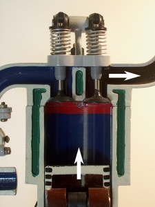
Exhaust: When the piston has reached the bottom of the power stroke, the exhaust valve (right) opens. The rotating crankshaft forces the piston upwards, pushing the combustion products out through the exhaust valve into the exhaust manifold. This corresponds to the cooling of the gas in the cylinder at constant volume (4). |
 |
A flywheel attached to the crankshaft keeps it rotating through the cycles during which the engine does not produce any work (i.e., intake, compression and exhaust). |
|
The numbers in parentheses after the processes listed above, refer to the steps in the thermodynamic cycle through which the gas inside the cylinder goes as the engine operates.
References:
1) Sears, Frances Weston and Zemansky, Mark W. College Physics, Third Edition (Reading, Massachusetts: Addison-Wesley Publishing Company, Inc., 1960) pp. 386-7.