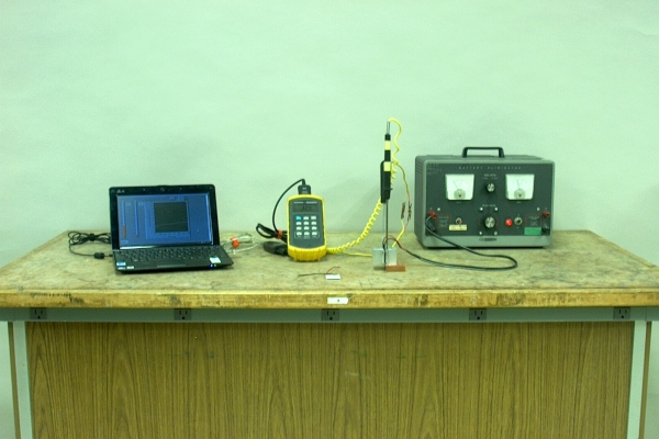
When you apply power to the Peltier element (mounted between the heat sinks, in the foreground, just right of center), both sides of which are initially at room temperature, one side becomes cooler, while the other side becomes hotter. A thermocouple inserted into each heat sink and connected to a dual-thermocouple thermometer, allows you to measure the temperature of each heat sink. A program running on a netbook connected to the thermometer, enables you to show the two temperatures, with a graph of their change over time, to the class. If you reverse the connections to the Peltier element, the hot side begins to cool, and the cold side begins to heat. Do not exceed 5 amperes! A naked Peltier element (in the foreground, above) is available for you to hold up to show the class (or for students to come look at afterwards).
Because different metals have different densities of electrons in the conduction band, when you place two dissimilar metals firmly together, some electrons flow from one metal into the other. The resulting charge imbalance between the two metals gives rise to a small potential difference between them, the magnitude of which is temperature dependent (because the density of the electrons in the conduction band of each metal is temperature dependent). This phenomenon is known as the Seebeck effect, named for Thomas Johann Seebeck, who discovered it in the early 1820s. It is the basis for a device called a thermocouple, a type of temperature sensor, two of which we use in this demonstration. It turns out that if you run current through such a junction, then depending on the direction of the current, the junction either emits heat or absorbs heat. This is called the Peltier effect, after Jean C. A. Peltier, who discovered it.
If one connects many thermocouples together in series, the potential difference across the string is much greater than that across a single thermocouple. Such a device, called a thermopile, is sensitive enough that one can use it to measure radiant energy. A string of thermocouples connected in this manner forms a series of junctions that alternate in direction. One set comprises the “hot” junctions, which together form the sensing element of the device. The other set comprises the “cold” junctions (or “reference” junctions), which sit at some reference temperature, lower than that of the sensor, at least when it is heated by the incoming radiation to be measured. As in the case of a single thermocouple junction, if one runs a current through such a device, depending on the direction of the current, one set of junctions begins to heat up, and the other set of junctions begins to cool. (Reversing the current flow changes which set heats and which set cools.) Such a device, known as a Peltier element, can thus be used as either a heater or a cooler. These are also known as Peltier heaters or coolers, thermoelectric heaters or coolers, or thermoelectric elements or modules. In most Peltier elements, the thermocouple junctions are actually semiconductor junctions of n-type and p-type bismuth telluride, antimony telluride and/or bismuth selenide. Because they are intended for different purposes, thermopiles and Peltier elements are constructed in different ways, but each comprises two sets of thermocouple junctions, connected as described above.
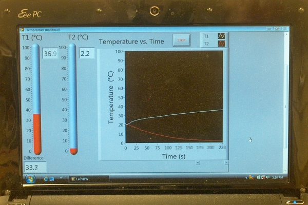
For this demonstration, a Peltier element mounted between two heat sinks is connected to a power supply. A LabView program running on a netbook, reads the temperatures from the digital thermometer, which is connected to two thermocouples, one on the hot side of the Peltier element, and one on the cold side. Clicking on the Arrow button at the left end of the tool bar (near the top of the screen, under the menu bar) starts the program. When you turn on the power supply, if it is not set at the 5-A maximum, you can slowly raise the voltage until you reach the desired current. Do not exceed 5 amperes! (The current reaches 5 amperes when you have applied aobut 2 volts to the Peltier element.) The photograph below shows the screen of the LabView program that reads the temperatures from the digital thermometer, and displays them.
References:
1) Sears, Francis Weston, and Zemanskey, Mark W. College Physics, Third Edition (Reading, Massachusetts: Addison-Wesley Publishing Company, Inc., 1960) pp. 601-5.
2) The Most Frequently Asked Questions about Thermoelectric Cooling
3) https://www.digikey.com/en/articles/choosing-using-advanced-peltier-modules-thermoelectric-cooling
