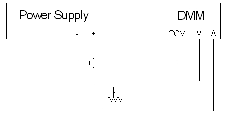
A large (1410-ohm) variable resistor is connected to a DC power supply (set at 20 volts) in series with the current input of the digital multimeter. The voltage input of the meter is connected across the power supply (in parallel with the resistor/ammeter combination). The large numerical display shows the readout of the meter. A schematic of this circuit is below. An overhead transparency of this schematic is available for display in class, or you can download a .pdf version of it here.
This demonstration illustrates Ohm’s law, which states that for a material whose resistance is constant regardless of the voltage applied to it, the current through it is directly proportional to the applied voltage, with the material’s resistance as the proportionality constant, or V = iR. (One can state this as the current, for a given voltage, being inversely proportional to the resistance, or i = V/R.) A material whose resistance remains constant regardless of the magntitude of the applied voltage (and thus the current flowing through it) is said to exhibit ohmic behavior.
You can slide the wiper of the variable resistor from the maximum value – about 1,300 ohms – down to about 145 ohms. To avoid the possibility of taxing the power supply or running too much current into the ammeter input, a wrap of electrical tape around the wiper bar prevents you from sliding the wiper any further than this.
By sliding the wiper from the end of the resistor to the middle, then to one-quarter the distance from the opposite end, etc., you can show that as you lower the resistance by half, the current doubles while the voltage remains the same. (You must switch between the DC V and DC mA settings to show voltage and current. Switching between these two settings does not affect the operation of the circuit. You can also choose any set of distances across the resistor to show whatever factor of change you would like.)