Each of the four capacitors shown above is connected in series with a 1-kilohm resistor. The galvanometer at left is wired as a voltmeter placed across the capacitor, and the galvanometer at right is wired as an ammeter, placed in series with the resistor and capacitor. When you connect each RC circuit in this way, then connect the battery across it, the time it takes for the voltmeter to reach its maximum, and the ammeter to reach its minimum, allows you to show the differences in charge time for the four capacitors, which have values of 10 μF, 500 μF, 2,000 μF and 20,000 μF. The switch sitting behind the two large electrolytic capacitors allows you quickly to replace the battery with a dead short to show the discharge of the capacitor. You may use this demonstration as it appears above, or with only a galvanometer wired as a voltmeter.
Whereas a constant current flows immediately in a resistor when you place it across a battery or other seat of EMF, in a capacitor, current initially begins to flow, but then diminishes with time. At the start, the capacitor is not charged. That is, there is no net charge on either of its electrodes, and there is no electric field inside it. When you place a (DC) voltage across the capacitor, as current flows, the capacitor begins to charge (that is, a negative charge develops on one electrode as an equal positive charge develops on the opposite electrode), and an electric field develops inside it. As the charge increases, the internal electric field, and, thus, the voltage across it, increases. This continues until the magnitude of the electric field inside the capacitor approaches that of the applied voltage, and the current approaches zero. How quickly this happens depends on the size of the capacitor – its capacitance, C, which equals q/V, where q is the charge on the capacitor and V is the voltage developed across it – and also on the size of the resistor in series with it (either the internal resistance of the battery or power supply, or, as in this demonstration, a resistor placed in series with the battery).
The voltage across the resistor and capacitor is V = VR + VC = iR + q/C, where V is the applied voltage (across both the resistor and the capacitor). Since the current, i, is dq/dt, this gives V = R(dq/dt) + q/C. The solution to this differential equation is q = CV(1 - e-t/RC). Since the voltage across the capacitor is q/C, we can also write this as VC = V(1 - e-t/RC), which gives us the voltage across the capacitor as a function of time. The product in the demoninator of the exponent, RC, is called the time constant, and is often denoted as τ. This is the time it takes for the voltage across the capacitor to reach 63% of the applied voltage. (At t = RC, the term in parentheses equals 1 - e-1, or 1 - 0.37 = 0.63.) To find the current as a function of time, we note that VR = V - VC = Ve-t/RC. Since VR = iR, we have i = (V/R)e-t/RC. (Differentiating q = CV(1 - e-t/RC) to get dq/dt = i, gives the same result.) After one time constant, it reaches 37% of its initial value.
Below is a plot of the voltage across the capacitor vs. time, for the situation where V = 5 volts:
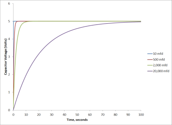
We see that the 10-μF capacitor reaches its maximum voltage almost instantaneously (RC = 0.01 s), the 500-μF capacitor takes about 2 seconds (RC = 0.5 s), the 2000-μF capacitor takes about 10 seconds (RC = 2 s), and the 20,000-μF capacitor takes on the order of 100 s (RC = 20 s).
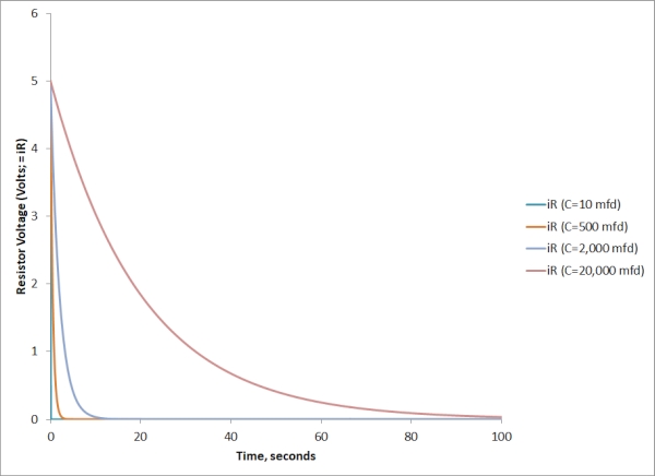
The current vs. time is as in the plot below:
Please note: The actual battery voltage in this demonstration is about 6 volts. (The battery is a 6-volt lantern battery.) The resistance of the galvanometer with its series resistor, however, is low enough compared to that of the 1-k resistor, to introduce a noticeable voltage drop across it. Because of this, the voltage displayed by the galvanometer is lower than the true battery voltage, and it draws a noticeable current, so that when the capacitor is fully charged, the current drops to some nonzero value. (Once the capacitor is charged, if you disconnect the galvanometer that reads the voltage across the capacitor, the current immediately goes to zero.) Otherwise, the behavior of the demonstration is exactly as it should be, and the response of the galvanometer(s) when you close the circuit shows very well the different behavior of the various capacitors.
Also, if you would like to do so, you can show the discharge behavior of each capacitor, once it is charged, by connecting the free end of the resistor to the free end of the capacitor. The switch in the foreground allows you quickly to disconnect the RC circuit from the battery, and almost immediately to short the circuit in this way.
References:
1) David Halliday and Robert Resnick. Physics, Part Two, Third Edition (New York: John Wiley and Sons, Inc., 1978), pp. 705-707.
2) Howard V. Malmstadt, Christie G. Enke and Stanley R. Crouch. Electronics and Instrumentation for Scientists (Menlo Park, California: The Benjamin Cummings Publishing Company, Inc., 1981), pp. 143-144.