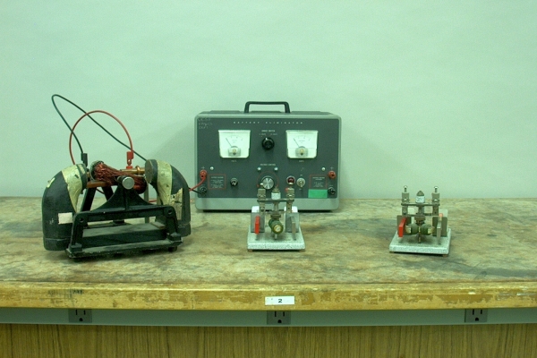
At left in the photograph is a home-made permanent magnet DC motor. In the center and at right are two Saint Louis motors made by CENCO.
Several demonstrations in this chapter (68.30 -- Electromagnet; 68.34 -- Cathode ray tube, coil; 68.45 -- Field of current-carrying coil, solenoid, toroid; 68.46 -- Magnetic fields of coils) show that, by running current through a coil, you can produce a magnetic field similar to that of a bar magnet. Demonstration 68.48 -- Torque on current-carrying loop, shows that if you place a coil in a magnetic field, oriented so that a current in it produces a magnetic field that is not parallel to that of the external magnetic field, the coil experiences a torque, which, if the coil is mounted so as to allow it, rotates the coil in whichever direction aligns its magnetic field with the external field. This means of producing torque finds practical application in electric motors, which use this phenomenon to convert electrical energy to mechanical energy, and thus, to perform mechanical work.
A permanent magnet motor is one in which a magnet, or pair of magnets, provides the static magnetic field in which the rotor rotates. The rotor consists of a central axle on which are mounted the armature coils and, to provide electrical contact, the commutators, to which the ends of the armature coils are connected. A pair of brushes, which touch the commutators, provides contact with the power supply. The simplest armature is a single coil, wound about an axis perpendicular to the motor shaft, with the windings symmetrical about the shaft, so that its magnetic field is perpendicular to the shaft. In the motor at left, the coil is flat, and the windings are close to the shaft on either side. In the middle motor, the coil is elongated, and it is wound around an iron core, which is mounted symmetrically about the shaft, with its (long) axis perpendicular to the shaft. When you apply power to the motor, the current flowing through the armature coil produces a magnetic field whose north and south poles are at opposite ends of the armature. These are repelled by the north and south poles, respectively, of the magnets, and attracted to their south and north poles, respectively, which causes the armature and shaft to rotate until the magnetic field of the armature aligns with the field of the magnets. Just as the armature lines up with the magnets, the gaps between the commutators arrive at the brushes. Inertia causes the armature to continue just past where it is aligned with the magnets, at which point the commutators have now switched places. The current in the coil thus reverses, causing the armature to be repelled/attracted through its next half turn. Thus, except for a small part of the rotation where the armature lines up with the magnet, and the brushes are very briefly in contact with both commutators, the current flow in the armature always causes the motor to rotate in the same direction. In which direction the motor rotates depends on the orientation of the commutators with respect to the armature coils (which determines which end of the coil is connected to which brush at any point in the rotation), and on the direction in which the power supply is connected (that is, which brush is connected to the positive terminal and which one is connected to the negative terminal). With this motor, you can reverse the direction of the motor by switching the positive and negative power supply connections.
The motor at right in the photograph has three armature coils. These are connected together, with a commutator at the junction of each pair of neighboring coils. For the motors with two armature coils (at left and middle), depending on the initial orientation of the armature, you may need to give the armature a tap to get the motor to start. With the one at right, one or another of the armature coils will always be oriented so that when you apply power to the motor, there is enough torque to start it. As shown in the photograph, if you connect the positive terminal of the power supply to the red banana jack on each motor (at right on all motors as they appear in the photograph; this is barely visible on the middle motor, and not visible on the one at right), and the negative terminal to the black one, the motor at left rotates clockwise, the middle motor rotates counter-clockwise as viewed from the top, and the motor at right rotates counter-clockwise as viewed from the top. (The north pole of the magnet is on the right of the large motor at left, and at left (red) in the other two motors.)