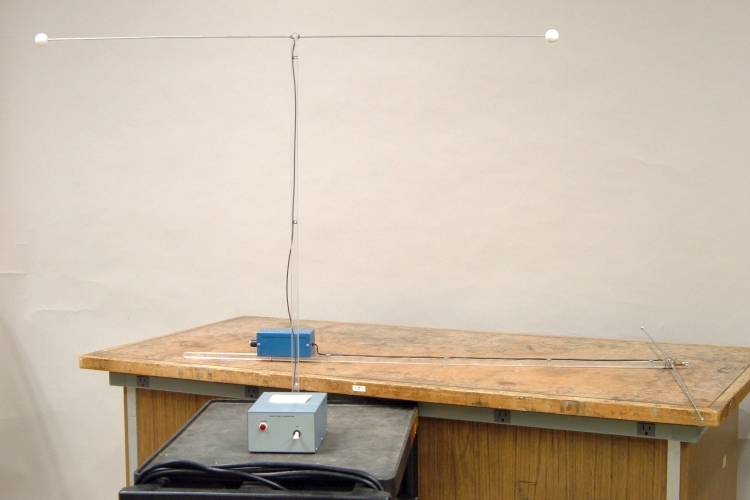
This demonstration shows the existence of radio waves by means of a low-power radio transmitter and a portable receiver that lights a light bulb to indicate reception of a radio wave.
In the photograph above, the light blue box in the center of the cart (with an upright lucite strut attached, which has a thin rod screwed into it on either side at the top) is a radiofrequency transmitter. It oscillates at 147.496 MHz, which corresponds to a wavelength of (2.998 × 10⁸ m/s)/(1.47496 × 108 cps) = 2.033 meters. (The output power is about 20 mW.) The two rods at the top form a radiating dipole, and their ends are one meter apart. This corresponds, at least fairly closely, to one half wavelength.
The unit with the smaller, darker blue box is a receiver. Mounted to either side of the top of the strut is a telescoping antenna, and at the top (in the middle) is a light bulb. For normal operation of the unit, each telescoping antenna half should be adjusted so that it is the same length as one of the antenna halves on the transmitter. When the (receiving) antenna is oriented so that an incoming radio wave can induce an EMF in it, the receiver turns on the light bulb. The brightness of the light bulb corresponds to the amplitude of the radio wave, i.e., the greater the amplitude, the brighter the bulb. A sensitivity setting allows you to adjust how much the brightness of the lamp changes with the amplitude of the incoming radio wave.
The antenna of the transmitter is a dipole antenna, to which the transmitter applies a sinusoidal voltage at 147.5 MHz. This sets up an oscillating electric field across the antenna, with a corresponding oscillating magnetic field perpendicular to it. These propagate together from the antenna as an electromagnetic wave – a radio wave. This wave propagates in all directions along a plane that cuts through the center of the transmitter’s antenna, perpendicular to its axis, with the oscillating electric field parallel to the antenna axis, and the oscillating magnetic field perpendicular to it. It travels with the speed of light, and its wavelength and oscillatory frequency are related by λ = c/ν, as noted above. When you orient the receiver’s antenna parallel to the transmitter’s antenna (but not along its axis), the transmitted radio wave induces an oscillating EMF in the receiver’s antenna, which sets up an oscillating current in the receiver. The circuit in the receiver then lights the bulb with a brightness that is, as noted above, proportional to the amplitude of the received radio signal.
The purpose of this demonstration is mainly to show the nature of radio waves, and one way to detect them. You can also illustrate the concept of resonance by changing the length of the telescoping antenna halves on the receiver. When their lengths match those of the antenna halves on the transmitter, you get maximum reception. If you make the antenna halves either much shorter or much longer than those on the transmitter, the light bulb dims noticeably.
For details regarding polarization and standing waves, please see demonstration 76.10 -- Polarization and standing waves with radio transmitter.