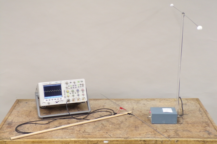
As noted in the page for demonstration 76.09 -- Radio transmitter lights antenna bulb, the light blue box in the photograph above (with an upright lucite strut attached, which has a thin rod screwed into it on either side at the top) is a radiofrequency transmitter. It oscillates at 147.496 MHz, which corresponds to a wavelength of (2.998 × 10⁸ m/s)/(1.47496 × 108 cps) = 2.033 meters. (The output power is about 20 mW.) The two rods at the top form a radiating dipole, and their ends are one meter apart. This corresponds, at least fairly closely, to one half wavelength. You can pick up the transmitted radio wave with the antenna at the end of the wooden rod. This antenna is connected to the oscilloscope via two taps near its center, so that you can display the received signal on the oscilloscope. By changing the orientation of the receiving antenna with respect to the antenna of the transmitter, you can vary the amplitude of the received signal.
The transmitter applies a sinusoidal voltage to its antenna at 147.5 MHz. This sets up an oscillating electric field across the antenna, with a corresponding oscillating magnetic field perpendicular to it. These propagate together from the antenna as an electromagnetic wave – a radio wave. This wave propagates in all directions along a plane that cuts through the center of the transmitter’s antenna, perpendicular to its axis, with the oscillating electric field parallel to the antenna axis, and the oscillating magnetic field perpendicular to it. It travels with the speed of light, and its wavelength and oscillatory frequency are related by λ = c/ν, as noted above. When you orient the receiving antenna parallel to the transmitter’s antenna (but not along its axis), the transmitted radio wave induces an oscillating EMF in the receiving antenna. A portion of this EMF appears between the two micrograbbers attached near the center of the antenna, which are connected to one of the oscilloscope inputs. The oscilloscope trace shows a sinusoid whose amplitude is proportional to the EMF induced in the receiving antenna. The amplitude of the transmitted wave decreases with distance from the transmitter’s antenna. At distances that are large compared to the length of the antenna, the amplitude decreases according to the inverse square law (see demonstration 76.06 -- Inverse square frame). Since the oscillating electric field is parallel to the transmitter antenna, and the oscillating magnetic field is perpendicular to it, the radio wave is polarized in the direction of the antenna, and zero along the antenna axis at either end. For any distance from the transmitter antenna, if you hold the receiving antenna parallel to it, the oscilloscope trace reaches a maximum, and if you turn the receiving antenna perpendicular to it, the trace approaches zero. If you hold the receiving antenna at either end of the transmitter antenna, parallel to it, the oscilloscope trace approaches zero. (See demonstration 76.10 -- Polarization and standing waves with radio transmitter.)