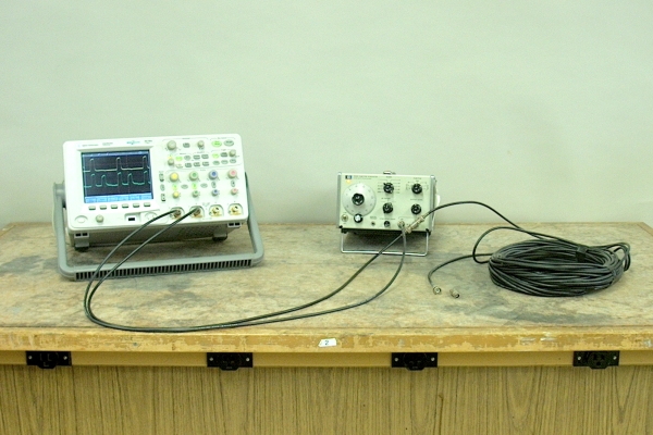

Two outputs of a signal generator are connected to two inputs of an oscilloscope. (The vertical scale on each channel is adjusted to give two traces with the same apparent amplitude.) A periodic pulse input into both channels of the scope displays identical signals. When a 100-foot length of coaxial cable (type RG-58A/U) is also connected to the second scope input by means of a BNC tee (at the signal generator), the scope input sees the pulse as it enters the cable, and its delayed reflection from the far end of the cable. Now also available are a five-foot cable and a 15-foot cable.
With a dead short at the end of the cable, i.e., a fixed end, the reflected pulse is inverted, so that we see the positive-going initial pulse followed by a negative-going pulse, separated by the round-trip time of the pulse through the cable. This is shown in the photograph below on the left.
With nothing connected to the cable, i.e., a free end, the reflection occurs in phase, so that we see the initial pulse followed by a second positive-going pulse, again separated by the round-trip time of the pulse through the cable. This is shown in the photograph below on the right.
The nominal characteristic impedance of RG-58A/U cable is 50 ohms. If you place a 50-ohm terminator on the end of the cable, then, you provide a load whose impedance matches that of the cable, and the pulse goes into the load with no reflection:
If you wish, you can show the class what happens when you remove the cable, in which case there is no reflected pulse (and the outgoing pulse is larger because you’ve removed the load from the signal generator):
The speed of light in vacuum is 2.998 × 10⁸ m/s, which is approximately equal to 1 ft/ns. In coaxial cable, the speed of an electrical signal is about 2/3 of this, or about 8 in/ns. So for a 100-ft cable, the round-trip time is about 300 ns, which is close to the measured time of 316 ns. This measurement is shown by two red, dashed vertical lines, one at the rising edge of the outgoing pulse and one at the rising edge of the reflected pulse, and the “ΔX = 316.000ns” at bottom left on the screen.
An earlier version of this demonstration used a square wave instead of a pulse train, with the period of the square wave such that each half cycle was on the order of ten times as long as the delay. You can also perform the demonstration this way to show the superposition of the square wave with its reflection.
With a dead short at the end of the cable, i.e., a fixed end, the reflection is 180 degrees out of phase with respect to the orignal signal, so that both half cycles of the reflected wave cancel with those of the input, except where they do not overlap because of the delay. One thus ends up with a trace that is zero everywhere except for a positive-going pulse at the leading edge of the input signal and a negative-going pulse at the end of the first half cycle, each having a width that corresponds to the round-trip time of the signal through the cable. This is shown in the photograph below on the left.
With nothing connected to the end of the cable, i.e., a free end, the reflection occurs in phase, so that cancellation occurs in those regions where the positive half cycle of one wave overlaps with the negative half cycle of the other. The duration of this overlap is, again, the round-trip time of the signal through the cable. This case is shown in the photograph below on the right.
As in the traces above, the two red, dashed vertical lines show the width of these regions, which on the scale of these traces, measures 320 ns.
If you add the 50-ohm terminator, the two traces look identical: