You can display simultaneously the AM carrier (actually one generated within the radio set; vide infra), the carrier modulated by the audio signal, and the audio signal separated from the carrier. These correspond to the top, middle and bottom traces, respectively, on the oscilloscope in the photograph above.
How does it work?
By setting up a sinusoidal voltage with the audio signal superimposed on it, a radio transmitter causes oscillatory motion of the electrons in an antenna, which creates an electromagnetic wave. This radio wave induces oscillatory motion of the electrons in the antenna of a receiver. The receiver then separates the audio information from the radio wave (vide infra), to be amplified and sent to loudspeakers for the listener to hear. Since they are electromagnetic waves, radio waves travel at the speed of light, and one can find their wavelength by the relation ν = c/λ, where c is the speed of light. A 1,000 kHz radio wave has a wavelength of (2.998 × 10⁸ m/s)/(1.000 × 106/s) = 299.8 m.
An AM radio wave consists of a sinusoidal carrier wave, which is modulated by an audio signal. The amplitude of the carrier wave fluctuates with the amplitude of the superimposed audio signal, hence the name “AM,” which stands for “amplitude modulation.” Since the audio signal is a complex sinusoid, that is, a superposition of many sinusoids in the audio frequency range, its superposition with the AM carrier generates bands of both sum and difference frequencies, called sidebands. Because the frequencies of AM radio stations are assigned at 10-kHz intervals on the AM band (520-1700 kHz), the FCC limits these sidebands to ±5 kHz. Radio stations stay within these limits by filtering from the audio signal any frequencies above 5 kHz.
It is fairly easy to select an incoming AM signal by tuning an LC circuit so that its resonant frequency matches that of the signal’s carrier frequency, then rectifying the signal and filtering out the radiofrequency components, then amplifying the resulting audio signal (more on this later). If one does this, then any amplifier stages before the detector that separates the audio signal from the carrier must be made to handle the entire AM band, and they must be tuned simultaneously. The selectivity of such a system would also be limited by the accuracy of the tuning of each stage. To overcome these problems, most radio sets tune an LC network to match the frequency of the desired radio signal, and simultaneously tune an oscillator to a frequency 455 kHz above this frequency. The incoming radio signal is then mixed with the oscillator output in a mixing amplifier to yield signals at the two original frequencies plus signals at sum and difference frequencies of them. Whatever the resulting signals are, one of them is always a modulated sinusoid at 455 kHz, the difference between the local oscillator frequency and that of the incoming radio signal. This is called the intermediate frequency, or IF. The IF passes through an amplifier designed to pass a narrow band centered at 455 kHz, then through a filter that removes what is left of all the other frequencies from the mixing amplifier, leaving the IF only. The IF then goes through a detector circuit, which separates the audio signal from the carrier (actually, it gives the top half of the modulated carrier) and then sends it through a filter that passes only audio frequencies. The cleaned-up audio signal is then amplified and sent to a loudspeaker (or loudspeakers), so that you can hear it.
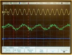
The three oscilloscope traces in the photographs below are the AM oscillator (AM OSC) on top, the IF (MOD_IF) in the middle and the extracted audio signal (AUDIO) on the bottom. The radio has been tuned to a station at 990 kHz.
In the photograph at left, the timebase is set to 1 µs/div, and we can clearly see the AM oscillator at 1.445 MHz (990 + 455 = 1.445 MHz), and the IF at 455 kHz (1.445 MHz - 990 kHz; the sum frequency at 2.435 MHz, and the original 990 kHz frequency are both filtered out). Since the audio frequency is 5 kHz or lower, so 1 cycle every 0.2 ms (200 µs) or longer, and the trace is only 10 µs wide, the IF and the audio trace below look essentially flat.
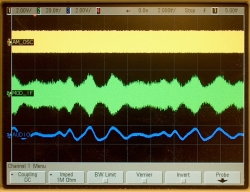
In the middle photograph, the time base is now 2 ms/div, and we can clearly see the modulation of the IF, and the shape of the audio signal below it. As we can also see, the audio modulation of the carrier results in a change in amplitude that is symmetrical about the horizontal axis. The top and bottom halves of the modulation contain the frequency information that results in the two aforementioned sidebands, one of which is separated out to give the audio signal.
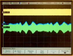
In the photograph at right, the bottom trace has been moved to line up with the top of the trace that shows the modulated carrier, and we can see that the recovered audio signal indeed matches it.
FM transmission
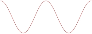
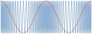
The physical process of FM transmission is virtually identical to that of AM transmission. The difference is that in FM, which stands for “frequency modulation” the audio signal modulates the frequency of the carrier instead of the amplitude. The graphs below show what this looks like:
→ The panel at left shows the unmodulated FM carrier with a sinusoidal audio signal above it. The right-hand panel shows the modulated FM carrier, with the audio signal superimposed to show the correspondence between the two. The FM band runs from about 88 MHz to 108 MHz. Since these frequencies are so much higher than audio frequencies, it would be impossible to capture this on the oscilloscope as above for AM. AM frequencies are, of course, also much higher than audio frequencies, but since with AM we are trying to observe a change in amplitude, it does not matter that we cannot resolve the individual cycles of the carrier. For FM, this inability means that we cannot observe the thing that is being modulated, at least not with an oscilloscope in the same manner as we can for AM.
References:
Thanks to Bob Pizzi for useful discussions, and for help in finding the proper test points inside the radio.
1) Horowitz, Paul and Hill, Winfield. The Art of Electronics (New York: Cambridge University Press, 1989), pp. 652-3, 894-900.
2) http://cnyack.homestead.com/files/modulation/modfm.htm
3) http://en.wikipedia.org/wiki/AM_broadcasting
4) http://en.wikipedia.org/wiki/Amplitude_modulation