Note: A smaller (and MUCH lighter) verion of this demonstration, shown below, is available for use in classrooms outside the Broida lecture hall building.
Two large mirrors are hinged together. This allows you to vary the angle between the mirrors, so that in addition to showing reflection from a single plane, with the mirrors at 90° you can show double reflection, and at smaller angles you can show multiple reflections and the results of odd and even numbers of reflections. (You can get double reflection even at angles greater than 90°, but the resulting image is then visible only over (a) narrow range(s).) The object and all its (virtual) images lie equidistant from each other on a circle whose center is the line between the two mirrors, in a plane perpendicular to that line. (This circle, of course, extends behind the mirrors.) The basis for the operation of this demonstration is that a mirror reflects light at the same angle in the opposite direction to its original path. That is, the angle of reflection equals the angle of incidence, where both angles are with reference to the normal to the mirror. For a light ray perpendicular to the mirror’s surface, the angle of incidence equals zero, as does the angle of reflection, and the ray is reflected back on itself. For any nonzero angle of incidence, the light ray emerges at the same angle on the opposite side of the normal.
Huygens’ Principle states that you can treat light as being, at a particular instant, a wavefront that comprises a continous line of point sources, each of which emits a secondary spherical wavelet, and that at some time after that instant, the line of tangency to all these secondary wavelets gives the new position of the wavefront. The direction of travel, and the light ray itself, is perpendicular to this line of tangency. By using this geometrical construct to model light reflecting from a mirror, if you keep the wavelength of the light (the distance between wavefronts) constant, you arrive at the aforementioned law of reflection.
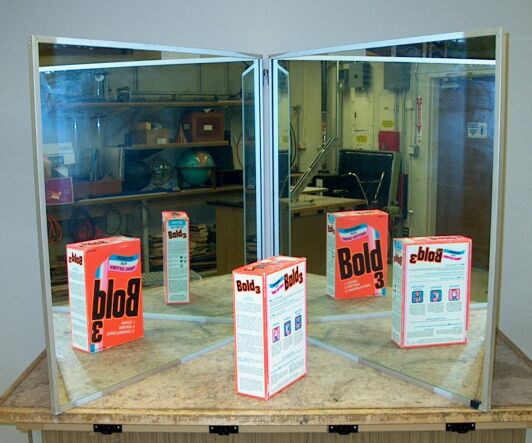
In the photograph above, the mirrors are at an angle that is perhaps around 68°. We see two images at the rear and two toward the front. We also see that for the two rear images, the printing on the box appears to be oriented properly from left to right, whereas in the front images, the printing appears to be reversed from left to right. The ray tracing below shows why this is so.
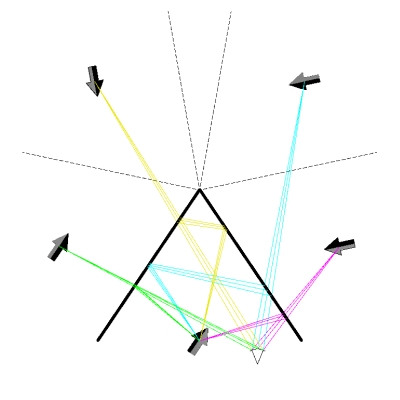
The heavy solid lines are the two mirrors, set at an angle of 68°, and the dashed lines are places where we see reflections of the mirrors themselves (which you can see in the photograph above). The inverted wedge with the arc, at bottom, right of center, represents the viewer’s eye. The arrow is rotated to match roughly the angle at which the detergent box is set in the photograph, and the image arrows are rotated to match this angle. The various ray bundles show the paths that light takes from the object to the viewer’s eye via the mirrors, to form the four images we observe. We can see that the two rear images are the result of double reflection. We see the orange front of the box (or black side of the arrow), which faces the left mirror, in the right one, and the left side of the box (head end of the arrow), which faces the right mirror, in the left one. As noted above, we also see that as a result of the double reflection, these two images appear from left to right as they would were we facing the box (or the arrow). The two front reflections, which are the result of single reflections off each mirror, appear from left to right as mirror images.
All of the images are visible from any place for which the path of the ray between the virtual image and the viewer passes through a mirror surface (and, of course, is not blocked by the object itself). For example, for the viewing position in the ray tracing above, if we move the viewer’s eye backward while maintaining the horizontal position, once we move it far enough that the rays shown in magenta go off the edge of the right mirror, the image at right front will disappear.
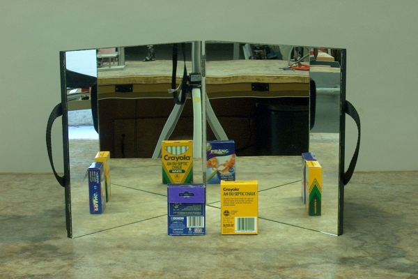
Below is a photograph of the smaller set of mirrors (each mirror is a 1-foot square mounted on 1/2-inch plywood), set at 90°.
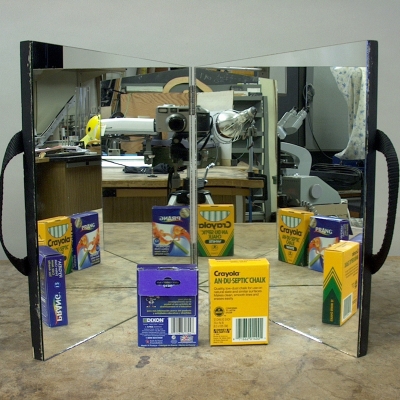
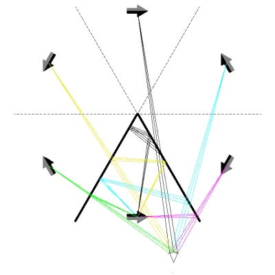
As you can see from the photograph, this mirror assembly has a pair of handles, so that it is easy to carry. We see three images, the rear one a result of a double reflection, and the two side ones the results of single reflections. To give a further idea of the workings of this demonstration, below is a photograph of the small mirrors set at 60°, and next to it a ray tracing that shows how the images are formed.
Here, we observe five virtual images. The rearmost image appears as a mirror image, the two middle images appear correct from left to right, and the two frontmost images appear as mirror images. We see that the rearmost image is a result of a triple reflection, the middle two are results of double reflections, and the front two are results of single reflections. The images formed by odd numbers of reflections appear as mirror images, while those formed by even numbers of reflections do not.
By closing the mirrors even further, you can get more even and odd reflections. Of course, the smaller the angle between the mirrors, the smaller the angle over which all the images are visible to the students. One solution is to rotate the apparatus (with the large one, you would turn the whole demonstration table) as necessary. Two mitigating factors are that you probably do not need to generate a large number of images to show the pattern – a 60° angle may be the smallest angle you need, and that as you close the mirrors and thus lose the images that are toward the front, you gain more images toward the back, and the reflections of the mirrors themselves project from the center line outward, so at least some portion of each is always visible, except if you are looking along or behind the plane of one of the mirrors (in which case those in whatever portion of the front of the other mirror is still exposed, are visible).
References:
1) Halliday, David and Resnick, Robert. Physics, Part Two, Third Edition (New York: John Wiley and Sons, 1977), pp. 943-945. The ray traces above are after figure 44-9 on page 962.
2) Sears, Frances Weston and Zemansky, Mark W. College Physics, Third Edition (Reading, Massachusetts: Addison-Wesley Publishing Company, Inc., 1960), pp. 790-791.
