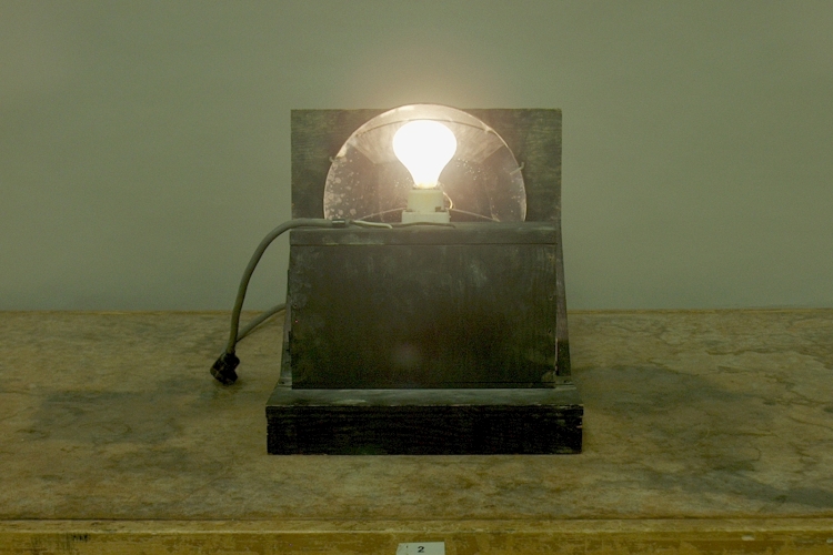
When you close the switch, an upside-down light bulb hidden within the black box lights, and the concave mirror forms an image of it, right side up, over an empty socket.
The front panel is hinged so that you can open it (from the right) to reveal the light bulb inside.Demonstration 80.12 -- Concave mirror focuses flame, shows the formation by a concave mirror of an enlarged, inverted image on a distant screen, of a candle flame placed at its focal point. Its web page describes in detail the formation of an image by a concave (spherical) mirror. It shows how the geometry of the mirror and rays incident on it from an object determine that its focal length is one-half its radius of curvature (f = r/2), and that the relationships of the object distance, image distance and focal distance to each other are given by the equation 1/o + 1/i = 1/f. It describes the use of F, the focal point (at distance f from the mirror) and C, the center of curvature (at distance r from the mirror) as reference points for ray tracing to find the image of an object placed at various distances from the mirror.
As we can see from the equation in the paragraph above, if we place the object at C, then o = r, and since f = r/2, i also equals r. If we place an object at C, then, it produces an image of equal size at C. The light bulb hidden inside the box is at a distance of r from the mirror, below the central axis. That is, it is below the point C. It thus produces an image above the axis, at the same distance r from the mirror. It is above C, and it is the same size as the light bulb. Thus, when you turn on the light bulb, its image appears above the empty socket placed on top of the box. When the light bulb is not on, all the class sees is an empty socket, but when you turn the light bulb on, it looks as if there is a lit bulb screwed into the socket. For most students, the vertical angle from which they view the apparatus should allow them to see the illusion, but only those seated within a fairly small horizontal angle with respect to the central axis of the mirror, will be able to see the illusion properly. Those students sitting at locations where the angle of reflection for which they would see an image places the outgoing rays from the light bulb outside the area of the mirror, will not see the image of the light bulb at all. Therefore, you will have to rotate the apparatus from left to right to allow the whole class to see the demonstration.
As noted above, the front panel of the box is set on hinges, with a detent at the right side, so that you can pull it open to reveal the upside-down light bulb that is sitting inside.
References:
1) Jenkins, Francis A. and White, Harvey E. Fundamentals of Optics (New York: McGraw-Hill Book Company, Inc., 1950), pp. 80-86.
2) Halliday, David and Resnick, Robert. Physics, Part Two, Third Edition (New York: John Wiley and Sons, 1977), pp. 963-8.