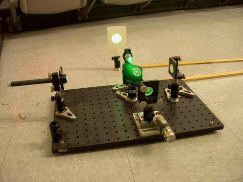
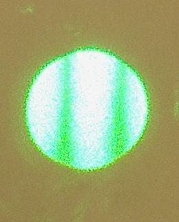
A green laser pointer with wavelength 532 nm provides a light source for this Michelson interferometer. The beam splitter in the middle of the apparatus transmits half of the beam to a fixed mirror and reflects the other half to a movable mirror. The movable mirror is mounted on a linear stage and can be moved by means of a hand micrometer with precision comparable to the wavelength of the light source. After reflecting from the mirrors, the two beams recombine at a screen. The difference in path length between the two beams produces a phase difference of 4πΔL/λ, where ΔL is the difference in the distances of the two mirrors from the beam splitter, and λ is the wavelength of the laser (note that the difference in optical path length is 2ΔL, but the factor of 2 was multiplied by 2π to get the factor of 4π). When the phase difference is an even integer multiple of π (0, 2π, 4π, ...) the beams interfere constructively and a bright fringe occurs in the center of the image on the screen. When the phase difference is an odd integer multiple of π (π, 3π, 5π, ...) the beams interfere destructively and a dark fringe occurs in the center of the image on the screen. Turning the micrometer a small amount changes the path difference between the two beams and thus causes the fringes to move.
The beams have some divergence; that is, barring the use of additional optical elements, the diameter of the beam increases the further it travels. The total energy is constant, so the greater the beam area the lower its intensity. Therefore there is a difference in intensity between the two beams in the interferometer due to their different path length. This difference affects how visible the fringes are. In the simple case of two mutually coherent beams with intensities I1 and I2, the maximum fringe intensity is given by Imax = I1 + I2 + 2(I1)1/2(I2)1/2, and the minimum fringe intensity is given by Imin = I1 + I2 - 2(I1)1/2(I2)1/2. These in turn define the fringe visibility V = (Imax-Imin)/(Imax+Imin). If I1 = I2, then the intensity of the bright fringes is maximized and the dark fringes have zero intensity. If I1 and I2 are signicantly different, then the difference between the light and dark fringes is less pronounced and the fringe pattern is thus harder to see. This is an issue in the setup pictured below.
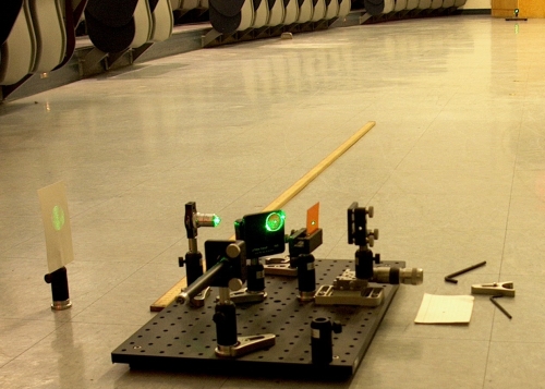
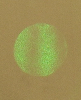
This is an alternate setup, where the fixed mirror is now far away from the rest of the interferometer. In the picture above, the mirror is about 25.5 m away (note the mirror in the top right corner of the picture). Interference fringes still appear, but because of the difference in intensities of the two beams an orange filter that decreases the intensity of the beam that took the shorter path is necessary to see the fringes.
One use of this setup is to motivate a discussion of coherence. For fixed fringes to appear on the screen, there must be a constant phase difference between the two beams. For an ideal monochromatic (single frequency) light source this would not be a problem, as it would produce a simple sinusoid with no discontinuities or changes in frequency. A realistic light source will have some finite spectral width, that is, it will consist of light of many different wavelengths. As the beam travels it loses its predictable sinusoidal shape because of the varying phase relationships of these different wavelength components. The maximum time after which one can still reasonably predict the overall phase of the beam is called the coherence time tc. The coherence length Lc is just ctc. The coherence time is related to the spectral width, Δf, of the source by tc = 1/Δf. The coherence length of the green laser pointer appears to be greater than twice the width of the lecture hall, thus one cannot determine the coherence length through this simple technique without using multiple mirrors. However, this setup does allow setting a lower limit on the coherence length and an upper limit on the spectral width of the laser. From the pictured setup, the coherence length appears to be at least about 25.5 m, thus the coherence time is at least 85 ns and the spectral width at most 12 MHz (this for a center frequency of about 560 THz).
With the long fixed-arm setup, the fringes can be seen to move slowly even when the mirrors are (nominally) stationary. This can be used as a demonstration of the thermal expansion/contraction of the floor of the lecture hall and of the aluminum optical breadboard. An object’s change in length, ΔL, from an original length of L for temperature change ΔT is ΔL = αLΔT, where α is the thermal expansion coefficient of the material. (α is around 2.1·10-5 to 2.5·10-5/°C for aluminum). Presumably, the lecture hall floor consists of concrete, among other materials; for reference, the Department of Transportation gives values of α of about 0.8-1.2·10-5/°C for Portland Cement Concrete). Note that other factors, such as frequency drift of the laser and motion of the air no doubt also contribute to varying degrees, but those effects would presumably not produce the same steady drift as thermal effects. In order to decouple the motion of the aluminum breadboard and the floor, one could observe the fringe drift speed when all the components are on the breadboard, then compare the fringe drift speed when the fixed mirror is placed far away. One could also place a flame or other heat source below or near the beam path in the long arm to see the effect of heating the air.
Changing the relative distance each beam travels is not the only way to change their relative phase. Changing the medium through which one beam travels will also change the phase difference. This can be done by placing an evacuated cell in the path of one of the beams, then slowly filling the cell with gas. The fringes will slowly move across the screen. Counting the number of fringes that pass by gives the phase shift due to filling the cell, where each complete cycle (light fringe to light fringe, or dark fringe to dark fringe, at a fixed point on the screen) corresponds to a 2π phase shift. This phase shift is related to the index of refraction, n, of the gas used to fill the cell by Δphase = 4πD(n-1)/λ, where D is the length of the cell and λ is the wavelength of the laser (both in the same units).