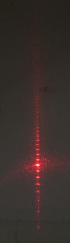
A laser beam reflected off the etched lines of a metal ruler produces a diffraction pattern like the one shown at right.
The page for demonstration 84.06 – Laser beam diffracted through various slits, shows patterns produced by diffraction from single slits, and from diffraction and interference from double slits. It also shows patterns formed by light passing through sets of two, three, four and five (equally wide, equally spaced) slits. These last four patterns provide a hint of what diffraction/interference pattern would be produced by a large number of narrow, parallel, equally-spaced slits. Such a device is called a diffraction grating. A diffraction grating is some type of substrate on which is etched (or deposited, depending on the method of production) a set of closely-spaced parallel grooves. If the substrate is transparent (e.g., plastic or glass), the incident light passes through, and the grating is a transmission grating. If the substrate is reflective or is coated with a reflective material (e.g., aluminum or gold), then incident light is reflected, and the grating is a reflection grating. Any object that reflects or transmits light, and has on it a pattern of uniformly spaced grooves or slits, can behave as a diffraction grating, as does the ruler in this demonstration.
As for the two-slit system, the locations of the (principal) interference maxima on a screen on which light coming from the grating is projected, are determined by the slit spacing and the wavelength of the light, and are given by the equation
d sin θ = mλ, where m = 0, 1, 2, . . .
d is the slit spacing, θ is the angular displacement of the particular maximum from the center of the pattern, and λ is the wavelength. m is called the order number. The central maximum is the zeroth order. Going outward from the center, located to either side are the first order, second order, etc. As for double slits, if D ≫ y, then sin θ ≈ tan θ ≈ y/D, and dy/D = mλ (or y = mλD/d; m = 1, 2, 3, . . .). This approximation does not hold for orders that appear far from the center of the screen.
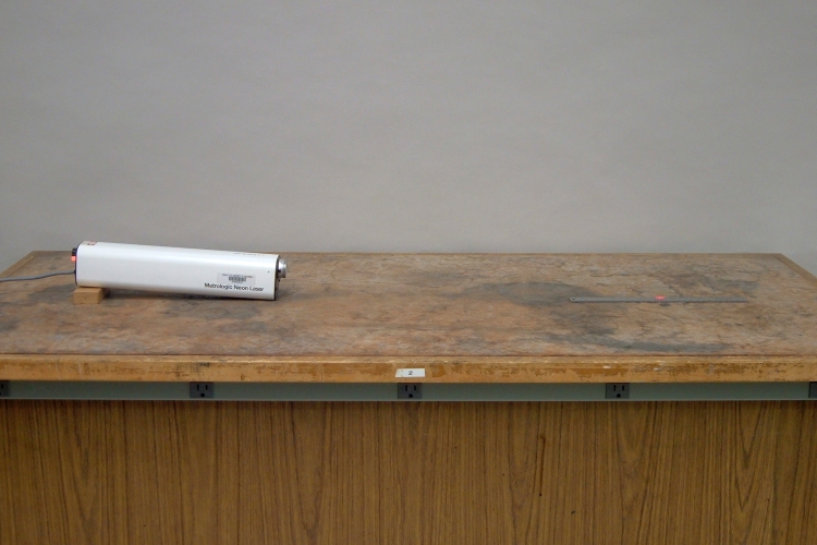
The ruler in this demonstration is a cork-backed steel ruler, etched along one edge in increments of 1/16 inch, and along the opposite edge in increments of one millimeter. The first inch is etched in increments of 1/32 inch. It is also possible to obtain a pattern from the longer marks at every 1/8 inch. If the ruler is not lying perfectly flat, this may distort the pattern. If this happens, holding the ruler down can make the pattern clearer. Besides the 12-inch/30-cm ruler shown above, a six-inch steel machinist’s rule is also available, if you wish to use it. Below are samples of the patterns you can obtain (rotated by ninety degrees).
1/8-inch rulings
(12-inch steel rule)1/16-inch rulings
(12-inch steel rule,
shown above)1-millimeter rulings
(12-inch steel rule)1/32-inch rulings
(6-inch machinist’s rule)1/64-inch rulings
(6-inch machinist’s rule)1/100-inch rulings
(6-inch machinist’s rule)References:
- 1) Halliday, David and Resnick, Robert. Physics, Part Two, Third Edition (New York: John Wiley and Sons, 1977), pp. 1047-8, 1051-2.
- 2) http://hyperphysics.phy-astr.gsu.edu/hbase/phyopt/grating.html#c1 and links to related material.
.jpg)
.jpg)
.jpg)
.jpg)
.jpg)
.jpg)