A video of this demonstration is available at this link.
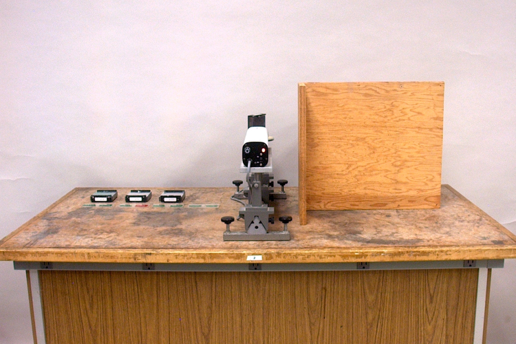
The laser in the photograph (center) is a helium-neon laser that emits light whose wavelength is 632.8 nm. Set on the platform in front of the laser, and on the table at left, are four reflection gratings, each of which has a different groove density. Their groove densities are 75, 300, 600 and 1,200 grooves/mm. When placed as shown, the grating projects the diffraction/interference pattern onto a screen to the right of the table. When the screen is at the appropriate distance, for the grating with 75 grooves/mm, 17 spots of the pattern fall across the entire width of the screen (sixteen spaces among them). For the grating with 300 grooves/mm, five spots span the width of the screen (four spaces among them). For the grating with 600 grooves/mm, three spots span the width of the screen (two spaces). For the grating with 1,200 grooves/mm, one spot falls at each edge of the screen. The wooden baffle at left blocks light from maxima that fall to the right of the screen, from going toward the class.
The page for demonstration 84.06 – Laser beam diffracted through various slits, shows patterns produced by diffraction from single slits, and from diffraction and interference from double slits. It also shows patterns formed by light passing through sets of two, three, four and five (equally wide, equally spaced) slits. These last four patterns provide a hint of what diffraction/interference pattern would be produced by a large number of narrow, parallel, equally-spaced slits. Such a device is called a diffraction grating. A diffraction grating is some type of substrate on which is etched (or deposited, depending on the method of production) a set of closely-spaced parallel grooves. If the substrate is transparent (e.g., plastic or glass), the incident light passes through, and the grating is a transmission grating. If the substrate is reflective or is coated with a reflective material (e.g., aluminum or gold), then incident light is reflected, and the grating is a reflection grating, as are the gratings used in this demonstration.
As for the two-slit system, the locations of the (principal) interference maxima on a screen on which light coming from the grating is projected, are determined by the slit spacing and the wavelength of the light, and are given by the equation
d sin θ = mλ, where m = 0, 1, 2, . . .
d is the slit spacing, θ is the angular displacement of the particular maximum from the center of the pattern, and λ is the wavelength. m is called the order number. The central maximum is the zeroth order. Going outward from the center, located to either side are the first order, second order, etc. As for double slits, if D, the distance from the slits to the screen, ≫ y, the distance of a point on the screen from the center of the screen, then sin θ ≈ tan θ ≈ y/D, and dy/D = mλ (or y = mλD/d; m = 1, 2, 3, . . .). This approximation does not hold for orders that appear far from the center of the screen.
The patterns formed by the gratings in this demonstration appear below. The fluctuating distribution in the intensity among the maxima is due to the fact that these particular gratings have been blazed. That is, the grooves are cut at a particular angle, called the blaze angle, chosen for a particular wavelength of light, to put a greater portion of the intensity into a particular order. These gratings are blazed for a wavelength that is different from 632.8 nm.
75 grooves/mm 300 grooves/mm 600 grooves/mm 1,200 grooves/mm Note that the spacings of the maxima are four times as great for the grating with 300 grooves/mm as for the grating with 75 grooves/mm, twice as great for the grating with 600 grooves/mm as for the grating with 300 grooves/mm, and twice as great for the grating with 1,200 grooves/mm as for the grating with 600 grooves/mm.
References:
1) Halliday, David and Resnick, Robert. Physics, Part Two, Third Edition (New York: John Wiley and Sons, 1977), pp. 1047-8, 1051-2.
2) http://hyperphysics.phy-astr.gsu.edu/hbase/phyopt/grating.html#c1 and links to related material.


