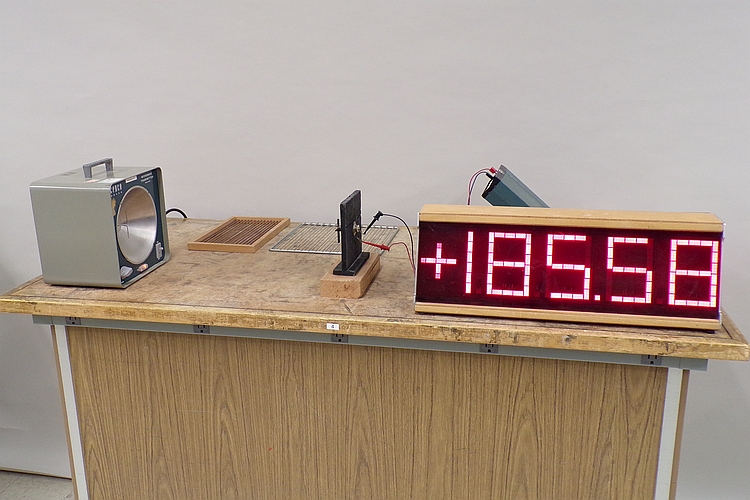
The transmitter shown above at left emits vertically polarized microwaves toward the right. The receiver mounted in the black wooden stand in the middle of the table detects them, and develops a potential across its output, which is proportional to their intensity. The output is connected to a multimeter, whose readout is shown on the large display. As shown in the photograph, both the transmitting antenna and the receiving antenna are oriented vertically. If you place either the metal grid or the wooden frame (shown at left, rear) between the transmitter and receiver, with the rods oriented vertically, this blocks the microwaves, and the meter reading goes to zero (or close to it). If you set it with the rods horizontal, the microwaves still reach the detector. If you turn the receiving antenna 90 degrees, the reading goes to zero. If you then place the grid or wooden frame with the rods at 45 degrees to the two antennas, some of the microwaves pass through and reach the detector.
The transmitter shown above is a CENCO microwave transmitter, which produces microwaves whose frequency is 2,450 MHz (2.450 GHz), and whose wavelength is about 12.25 cm. It has a half-wavelength dipole antenna, oriented vertically in the center of a parabolic reflector. The antenna is visible in the photograph above. The receiver also uses a half-wavelength dipole antenna, which is also oriented vertically and is also visible in the photograph. Please note that the transmitter is a vacuum tube device, so after you turn it on, it takes some time for it to start emitting microwaves, and several minutes for the amplitude to stabilize. (The heart of the unit is a General Electric 2C40-A planar triode, also known as a “lighthouse tube” because of its appearance. You can see its data sheet here.)
The physics of this system is essentially identical to that of the radio transmitter and receiver setup in demonstration 76.10 -- Polarization and standing waves with radio transmitter. The transmitter, as noted above, has a vertically-oriented half-wavelength antenna, which sets up a vertical oscillating electric field. This produces a horizontal oscillating magnetic field, and the two propagate together as an electromagnetic wave, along the line between the transmitter and the detector. Since the electric vector of this wave is oriented vertically, the wave is vertically polarized. In order to detect this wave, then, the antenna of the receiver must also be oriented vertically. In the photograph, both antennas are oriented vertically, and the output of the receiver is at its maximum.
Shown above, at the rear of the table, is a steel grid with parallel rods (which came with the transmitter and receiver) and a wooden frame with parallel steel rods set in it. With the apparatus as shown in the photograph, if you place either of these grids between the transmitter and receiver (with its plane perpendicular to the line between them) with the rods horizontal, that is, perpendicular to the two antennas, there is no change in the meter reading; the microwaves still reach the detector. If you now turn the grid so that the rods are vertical, they are now parallel with the oscillating electric vector of the microwaves, and the grid absorbs them; they no longer reach the receiver, and the meter reading goes to zero (or close to it).
If you now remove the grid, and turn the receiver 90 degrees (about the line between it and the transmitter antenna), so that its antenna is now horizontal, the antenna cannot interact with the microwaves. The receiver no longer receives the microwaves, and the meter reading goes to zero. With the receiver still oriented this way, if you now insert one of the grids as before, but with the rods at 45 degrees to the transmitter and receiver antennas, the meter now reads a voltage. The grid placed with the rods vertical would absorb the microwaves, and prevent them from reaching the receiver. The grid placed with the rods horizontal would pass the microwaves, but the horizontally oriented receiving antenna would not absorb them. With the grid rods at 45 degrees to the antennas, however, the vertically polarized microwaves now have a component that is parallel to the grid rods, and another component that is perpendicular to them. The grid absorbs the parallel component, but passes the perpendicular component. This component is also 45 degrees to the receiving antenna, and thus has a (horizontal) component that is parallel to it. The receiving antenna can absorb this component, and we see a reading on the meter. This is similar to what happens when you place two crossed polarizers (i.e., at 90 degrees) in front of a light source, and then place between the crossed polarizers a third, whose easy axis is at 45 degrees to theirs. (See section 1) Polaroid sheets (polarizers) in the page for demonstration 84.36 -- Polarizers). It is exactly what happens in the Polarization section of demonstration 76.10.