(Thanks to Prof. Tony Zee for the request that I build this demonstration)
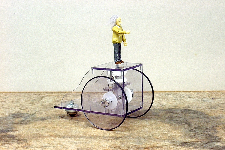
The purpose of this demonstration is to illustrate parallel transport of a vector, and in connection with this, to introduce the concept of a geodesic (the path having the shortest distance between two points on a surface). These are both important in characterizing Euclidean space, and are therefore also essential to relativity theory. (Hence the Einstein figure mounted atop the carriage.)
The south-pointing carriage, perhaps more commonly known as the south-pointing chariot, was a navigation aid whose origins are somewhat shrouded in legend and mystery. There is at least one account as early as about 1100 B.C.E., involving King Ch’êng, of the Chou, who was visited by members of the Yüeh Shang tribe, who wished to pay them tribute. The Chou court accepted, and in turn sent them back home loaded with gifts, among which are mentioned five south-pointing chariots, given to the Yüeh Shang lest they lose their way home. There are later accounts of the method of construction of these devices having been lost, and of later chariots, inside which someone would sit to adjust a pointer that maintained the south direction reference. The two designs about which perhaps the most is known are those of Yen Su, made at the end of the year 1027 C.E., and Wu Tê-jên, from 1107 C.E. It is clear from their descriptions that these chariots had some sort of internal mechanism of gears and levers, by which the rotation of the wheels of the chariot kept the pointer oriented in its original direction, by turning it by the proper amount and in the appropriate direction as the carriage rounded curves. The latter of these two designs may have involved differential gearing of some type, but this is not obvious. Links to references that describe these mechanisms are below.
People who used these chariots would set the pointer so that it faced south (the preferred direction in the region where they were popular), hitch the device to a horse, or team of horses, and then set off on their journey.
In 1947, a British automaker named George Lanchester introduced a design based on his earlier proposal that a south-pointing chariot could be made that used a differential as the connection between the wheels and the pointer. It is this design on which the model in this demonstration is based. The scale of this model, with respect to the actual vehicles mentioned above, is perhaps about 1/12.
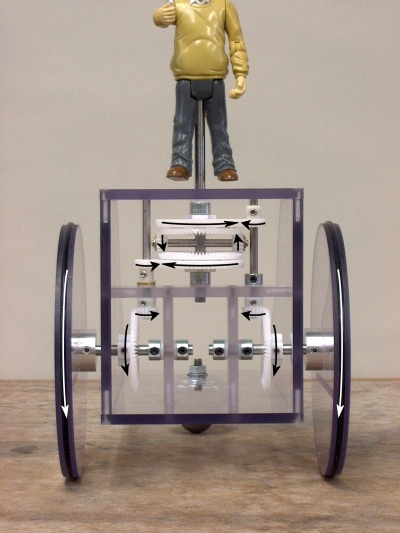
At left is a view of the front of the carriage, showing all the gears and their interconnections. The arrows show the directions in which the wheels and gears turn when the carriage is moving forward in a straight line.
Each wheel turns a bevel gear, which in turn rotates a pinion gear that is connected to a vertical shaft, on which is also a spur gear, which turns a larger spur gear in the center of the carriage. Each of these large spur gears is attached to a bevel gear to make a crown gear, and these are mounted with their teeth facing each other on a central shaft on which they can spin freely, which protrudes through the top plate of the carriage and bears the Einstein figure on top. Between the crown gears run two pinion gears, one at each end of a cross shaft that runs through the central shaft. These crown gears and pinions make up the differential.
The bevel gears on the wheel axles, and the crown gears, all have the same number of teeth, and the pinions and spur gears on the vertical shafts all have the same number of teeth, so the gear ratio between each wheel and its crown gear is 1:1. So for each rotation, each wheel turns its crown gear one full rotation. When the carriage is moving in a straight line, the two wheels turn their respective crown gears in opposite directions, as shown by the arrows. Since the crown gears are moving at the same speed, the instantaneous velocities at the top points and bottom points of the pinions are equal but opposite, so the average velocity for the pinions is zero, and they merely rotate in place. Thus the cross shaft does not turn, and the pointer (Einstein figure) remains fixed.
If the carriage goes around a curve, the wheels no longer turn at the same speed, so the crown gears turn at different speeds. The pinion gears rotate the cross shaft about the center axis at half the difference in speed between the crown gears, thus turning the pointer so that it maintains its original orientation.
With 1:1 gearing from each wheel to the differential, there is an important geometrical constraint on the construction of the carriage. The wheel diameters must be exactly equal, and the wheelbase (the distance between the two wheels) must exactly equal the wheel diameter. An easy way to understand how this carriage works is to imagine two cases. First, as described above, when the carriage is moving in a straight line, either forward or backward, the two crown gears rotate at equal and opposite velocities, so the pinion gears rotate in place, the cross shaft does not turn, and the pointer stays in position. For the second case, we imagine braking one wheel and allowing the carriage to turn in a circle about the braked wheel. Since the wheelbase equals the wheel diameter, the outer wheel must make two complete rotations for one full rotation of the carriage, thus turning its crown gear through two full rotations in the opposite direction to that of the carriage rotation. (You can see this if you look at the arrows in the photograph and imagine the carriage turning.) The braked wheel does not turn its crown gear at all. Since the pinions move about the center shaft at half the difference in speed between the two crown gears, they go through one full rotation, rotating the cross shaft, and thus the Einstein figure, one full rotation in the opposite direction to that of the carriage rotation. This mechanism works not only for these two special cases, but for all intermediate cases as well.
If we take the pointer (Einstein with his chalk hand outstretched) to represent a unit vector, we see that however we move the carriage, though the vector is displaced from its original position, it still points in its original direction. It is thus transported in parallel fashion.
This carriage has some interesting properties. First, though this may seem obvious, it works on any flat surface. It will also work on a curved surface whose radius of curvature is extremely large compared to the wheel base of the carriage. For example, a chariot with a two-meter wheelbase traveling on the earth, whose radius is about 6,370 km, so almost 3.2 million times larger than its wheelbase, will exhibit insignificant error. (Local curvature, on the other hand, might be much more important.) It will also work on any curved surface, no matter how greatly curved (as long as, of course, the curvature is not so great as to cause the carriage to “bottom out”), if it is traveling along a geodesic – the shortest path between two points. You can imagine placing this model, whose wheelbase is six inches, on, for example, a 16-inch globe. If you wheel the model along a great circle, such as the equator, each wheel travels a shorter distance than the body of the carriage, but since the wheels are equally spaced about the great circle, this path difference is the same for both wheels. Therefore, they turn at the same speed, and the pointer keeps its orientation. If you tried this on any other path, for example a circle about one of the tropics, the wheels would travel at different speeds, and the pointer would rotate as the carriage went.
It is interesting to note that Alan A. Mills, in “The Lodestone: History, Physics, and Formation ,” Annals of Science, Vol. 61, Issue 3, 2004, citing the work of Joseph Needham, states that the first text that clearly describes the magnetic compass needle is a Chinese work from about 1080 C.E., which is only about 50 years after the chariot of Yen Su, and slightly earlier than that of Wu Tê-jên. It is possible that the use of the south-pointing chariot overlapped with the use of the magnetic compass by as much as three hundred years.
A humorous note:
A well-known figure in the engineering world likes to use the south-pointing chariot as an example of technology that is needlessly complex, and which represents what one should not do when trying to make innovations in design. In fact, in his own company, when he and his design group are looking for a solution to a technical challenge and someone presents an idea, he responds, “It’s great, but is it a south-pointing chariot?” (You can find this on page 34 (printed page 32), in an article titled Dean of Engineering, which begins on page 30 of Make Magazine, Vol. 4.) Who is this person? He is Dean Kamen, the inventor of the Segway, the two-wheeled electric vehicle that one rides standing upright on a platform that sits between the wheels. You can find references to his comments on the south-pointing chariot here and here, among other places. The Segway is, of course, an ingenious device, but it is somewhat difficult to avoid wondering if it was really necessary to use all the gyros, servomotors and microprocessor power necessary to run the Segway and keep it upright, instead of adding an auxiliary wheel or two. (In Kamen’s defense, it is this technology that enabled him to design the stair-climbing wheelchair, which is quite useful.)
References:
James Foster and J. David Nightingale, in Appendix B of A Short Course in General Relativity, Third Edition (New York: Springer Verlag, 2006), give a thorough development of the mathematics that describes the workings of this device on a plane, on a surface and on a trip at constant latitude around a sphere. If you are using a computer that is connected to the UCSB network, you can view or download this appendix here. (It is part of the back matter, accessible via the menu on the left side of the page.)
You can find a mathematical description of the workings of the carriage as described above (for a different design) here. (This corresponds to part of the treatment in Foster and Nightingale.)
An interesting web site that has links to various pages with history of the south-pointing chariot, photographs and drawings of various models incorporating different designs, and a page of links and references, is here. (You can find what looks like an older version of this page here.) Especially interesting are the history (here) and the Model Builder’s Repository (here; at the link that reads “And now: Build your own !” on the main page above).
Another site with interesting designs and references is here, and, of course, there is a Wikipedia entry here.
You can view an interesting paper on the history of the south-pointing chariot by A.C. Moule (from a UCSB computer) here.
A rather fascinating book called “Tungking,” by William Mesny, Major-General in the Imperial Chinese Army, published in 1884, is available from Google Books here. Chapter II gives an account of the visit of the members of the Yüeh Shang tribe to King Ch’êng described above.
