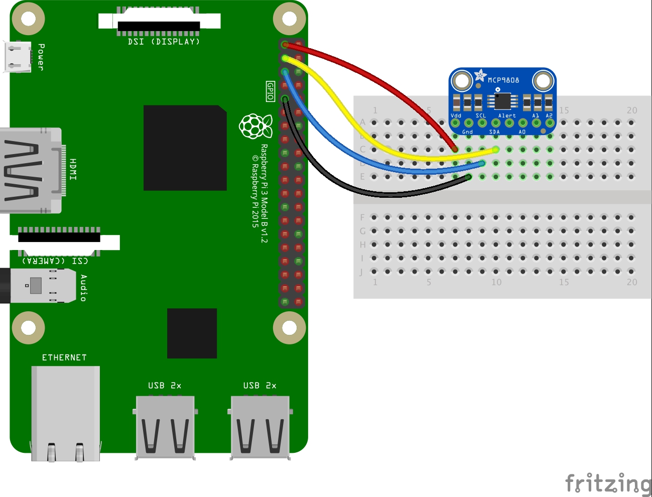
7. Using the 4 wires, connect the RPi pins shown in the diagram to the corresponding pins on the board. *** DO THIS CAREFULLY! *** If you power up with the wrong pins connected, you can destroy your RPi. In particular, be certain you are using the 3.3 V pin on the upper left of the two rows of pins, NOT the 5 V pin at the upper right. Also, BE CERTAIN you have not connected the 3.3 V or 5 V pins to ground! 8. If you are using the ADS1015, get the solar cell from your hardware kit. Identify the positive wire on the back of the solar cell, and connect it to pin A2 on the ADS1015. Connect the negative wire to pin A3. If you place the solar cell in direct sunlight while it is connected to the ADS1015, you could destroy the board, so avoid this. 9. Check your connections. Once you are absolutely sure you have wired the correct pins on the RPi to the corresponding pins on the board, check your connections. 10. Now you've got to ask yourself one question: "Do I feel lucky?" Regardless of the answer, check your connections. When you feel you can no longer take the pressure, take a deep breath and check your connections. Then plug in and boot up your RPi. 11. If your RPi boots up, you have not destroyed it. Be careful not to let the I2C device board pins touch anything conductive. 12. If you are using the MCP9808, run tempdemo.py from the course Python directory. If you are using the ADS1015, run adcdemo.py. If you see a series of temperature or voltage readings, congratulations! You have correctly connected the I2C device.