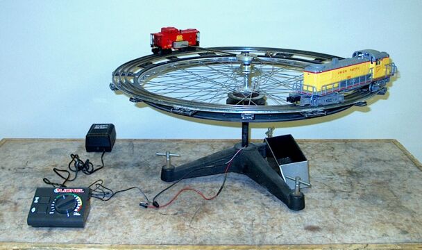
A toy train engine and caboose sit on a rotatable track. By means of the speed control (at left rear in the photograph), set the train in motion. As the engine and caboose travel around the track, the track moves in the opposite direction. If you now stop the train by depressing the stop/reverse switch (the one with the
symbol next to it), both the train and the track come to a stop. (You should also be able to slow the train gradually, but because of friction in the apparatus, the sudden stop gives a better result.)
Whereas an object moving in a straight line has linear momentum, p, equal to mv, where m is the object’s mass and v is its velocity, an object moving in a circular path possesses angular momentum, l, equal to mvr, where m is the object’s mass, v is its instantaneous linear velocity, and r is the radius of the circle in which it is traveling.
Strictly speaking, this is a vector quantity, l = r × p (and p = mv), but here we will consider the magnitudes and senses only. v is always tangent to the track, either counterclockwise or clockwise, and l points either up or down. According to the right-hand rule, if an object is moving in a clockwise direction as viewed from above, l points upward, and if it is moving counterclockwise, l points downward. Also, it bears noting that for an object moving in some other path relative to the origin of the coordinate system, the magnitude of the angular momentum is p(r sin θ), where θ is the angle between p and r; r sin θ is the perpendicular distance from the origin to the line on which mv lies (or the component of r that is perpendicular to the line of action of p). (It can also be written as r(p sin θ), where p sin θ is the component of p that is perpendicular to r.) Angular momentum is often called moment of (linear) momentum, and r sin θ is often called the moment arm. For an object moving in a circle, the instantaneous velocity, and thus momentum, is always perpendicular to r, so sin θ always equals 1, and l = mvr. This type of angular momentum is referred to as orbital angular momentum.
For an object moving in a circle, angular momentum may be expressed in terms of ω, the angular velocity of the object, whose magnitude equals v/r. l = mωr2, or l = mr2ω. All points on a rigid body rotating about a particular fixed axis move in circles about that axis with the same angular speed, and an instantaneous linear speed that is proportional to their distance from the axis. The angular momentum of the body is:
L = (m1r12 + m2r22 + · · ·)ω = (Σ miri2)ω
in which the sum (Σ miri2) is denoted I. This quantity is known as the rotational inertia or moment of inertia of the body with respect to the axis about which it is rotating. The expression for the angular momentum becomes L = Iω. We see that I depends not only on the mass of the object, but also on how it is distributed; the farther it is from the rotation axis, the greater its contribution to I. The angular momentum of a rotating body is referred to as spin angular momentum.
The expression for angular momentum is analogous to that for linear momentum. The moment of inertia is analogous to mass, and the angular velocity is analogous to linear velocity. These are analogous, but it bears noting that while for linear momentum, p is always parallel to v, this may not necessarily be the case for L and ω. If an object is mounted on a pivot that does not lie along one of its principal axes, then L will not be parallel to ω. A classic example is something called a skew rod. This is a rod that has a mass at each end, both equal, and mounted on a pivot at the center so that the long axis of the rod is not perpendicular to the pivot axis, but is set to that the perpendiclar line through its center (in the plane of both the pivot axis and the rod) lies at an angle α with respect to the pivot axis. As the rod rotates about the pivot, ω lies along the pivot axis, but L lies at an angle α with respect to ω, and rotates about the pivot axis with the angular speed ω. This creates a rotating torque about the pivot, perpendicular to ω, which would cause the spinning rod to wobble unless the pivot were properly reinforced. When the rod is stationary there is no torque on it, and it is statically balanced, but when the rod spins, there is a rotating torque, which causes it not to be dynamically balanced. To avoid excessive vibration and wear, rotating machine parts must be designed for dynamical balance. This is why, for example, after mechanics mount tires on vehicle wheels, they use dynamic balancing to determine where to add mass to make sure that L and ω coincide.
Just as we can change the linear momentum of an object by applying an external force, we can change the angular momentum of a rotating object (or one moving in a circle) by applying an external torque. For an object moving in a straight line, the time rate of change of momentum is equal to the applied force, or F = dp/dt = d(mv)/dt, which for constant mass gives the familiar F = ma. For an object moving in a circle, the time rate of change of angular momentum is equal to the applied torque, or τ = r × F. r × F = r × dp/dt. If we differentiate l = r × p, above, we find that τ = dl/dt (as we should expect). For a rotating rigid body whose moment of inertia is constant, τ = dL/dt = I(dω/dt), or τ = Iα. (The page for demonstration 28.24 -- Angular acceleration, gives a more detailed derivation of this, based on the work done by the applied torque, and the resulting change in kinetic energy of the rotating body.)
We could consider the motion of the toy engine and that of the caboose separately. Since the caboose has inside it lead strips to set its mass equal to that of the engine, though, they comprise a system of two equal masses joined by a pair of struts, which move in a circle whose center is at the center of mass of the system. Hence we may consider them as a single object rotating about its center of mass. Its moment of inertia is 2Mr2, where both the engine and the caboose have mass M, and r is the distance of both the engine and the caboose from the center. Here we are ignoring the mass of the strut assembly. The center of mass of this assembly is also at the center, so it, too is a rigid object rotating about its center of mass. Its moment of inertia adds to that of the engine-caboose pair. In what follows, “(toy) train” refers to the engine, caboose and strut assembly together.
Just as linear momentum must be conserved, so must angular momentum. The system comprising the toy train and bicycle wheel track starts with zero angular momentum. When you dial up the voltage on the speed control to start the toy train in motion, the train exerts a torque on the track, causing it to rotate. In accordance with Newton’s third law of motion, the track exerts an equal and opposite torque on the train. Thus, as the train goes around the track in one direction, the bicycle wheel and track rotate in the opposite direction. Each now possesses angular momentum equal to that of the other, but with opposite sign. Whatever the speeds of the train and track are, the angular momentum of the apparatus remains zero. If you now stop the train as described above, in coming to a stop the train exerts a torque on the track in the opposite direction to the torque it exerted before. The track exerts an equal and opposite torque on the train, and the train and the track both come to a stop.
References:
- 1) Young, Hugh D. and Geller, Robert M. Sears & Zemansky’s College Physics, 8th edition (San Francisco: Pearson Education, Inc./Addison Wesley: 2007), pp. 305-309.
- 2) Resnick, Robert and Halliday, David. Physics, Part One, Third Edition (New York: John Wiley & Sons, Inc., 1977), pp. 231-245.
- 3) Kleppner, Daniel and Kolenkow, Robert. An Introduction to Mechanics, Second Edition (Cambridge, UK: Cambridge University Press, 2014), pp. 296-299.