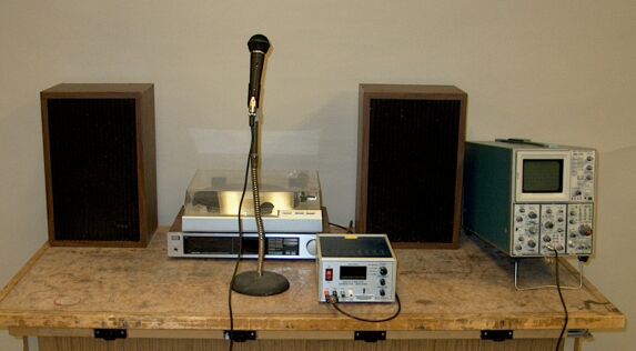
You can play either a radio station, a record on the phonograph, or a tone from the signal generator. The microphone picks up the sound from the speakers, and the resulting electrical signal is displayed on the oscilloscope.
Shown in the photograph above is a stereo system, which consists of an AM/FM receiver, turntable and speakers. Connected to the auxilliary input of the receiver is a function generator. This arrangement allows you to play a radio station, a record on the turntable, or the tone produced by the function generator. The microphone sitting in front of the stereo system, connected to one channel of the oscilloscope, converts the sound into an electrical signal, which you can display to the class. This demonstration illustrates the conversion of the electrical signal from the output of the stereo system into sound by the speakers, and then the conversion of sound from the speakers by the microphone back into an electrical signal for display on the oscilloscope. It also allows you to show the class how that electrical signal looks, and depending on what you play through the speakers, you can show how certain properties of that signal relate to the sound that you and the class are hearing.
The speakers are similar to those described in demonstration 68.54 -- Loudspeaker. This type of speaker has a paper cone, which is set vibrating by means of a voice coil connected to its back end. The voice coil sits between the pole pieces of a magnet, and the fluctuating current produced by the audio signal causes the coil to move back and forth in the magnetic field. As the coil oscillates, so does the cone, which produces a series of compressions and rarefactions in the air in front of it, that is, a sound wave. Inside each speaker cabinet is a large speaker, called a “woofer,” whose frequency response is weighted toward the lower end of the audio range, and a smaller speaker, called a “tweeter,” which responds more greatly toward the higher end of the audio range. The two are connected to the amplifier via an RC network called a “crossover network,” which passes more of the lower frequencies to the woofer, and more of the higher frequencies to the tweeter. (Some systems also have a third speaker specifically for the mid-range frequencies.) The microphone is a type called a dynamic microphone. The working element in this type of microphone is essentially a small speaker operated in reverse. Incoming sound causes the cone to vibrate, which moves the voice coil. The motion of the coil in the field of the magnet induces a fluctuating voltage across the coil.
The audio signals that you can display in this demonstration have gone through different series of steps before being coverted to sound by the speakers. The function generator does not itself produce sound, but it produces an electrical signal which, when amplified and sent through the speakers, produces a sound wave.
A phonograph has a rotating platter on which one sets a vinyl record, and a tone arm at the end of which sits a cartridge with a stylus. The record has impressed on its surface a fine spiral groove in which the stylus rides as the platter turns. Along the groove is a pattern that causes the stylus to vibrate (the walls of the groove are “wavy”). As the stylus vibrates, it causes a magnet (or pair of magnets) to vibrate near a set of coils, inducing a fluctuating current in them. This signal is then amplified and sent to a pair of speakers. There are other types of cartridges, which work different ways, but this particular type of magnetic cartridge is probably the most common. (Some magnetic cartridges move the coils instead of the magnets. Crystal and ceramic cartridges use the piezoelectric effect to produce a changing voltage. The vibrating needle creates fluctuating distortions in a crystal or ceramic element, which generates a fluctuating voltage.) The process by which the groove is made is somewhat complicated. Whatever sound is to be recorded, is converted into electrical signals by microphones. Without going into the details of how these signals are recorded, processed and mixed, suffice it to say that the result is sent to a device called a record lathe. This apparatus has a turntable, on which is set a lacquer-coated aluminum disc. Riding on the surface of the disc is a cutting stylus, which vibrates according to the electrical signal that it receives. As the disc rotates, the head with the cutting stylus is moved toward the center, so that the stylus cuts a spiral groove. The resulting disc is then cleaned, coated with silver, and electroplated with nickel, to make a disc that has a negative of the groove (a raised ridge, instead of a groove), which is then separated from the lacquer-coated disc. Depending on the particular process, this negative may be used as a stamper, or it may again be electroplated to make another positive copy, and the process repeated to make another negative copy, this time with a chromium surface, to make the stamper, which is then used to press records. The record press holds two stampers, one for each side of the record, between which is inserted a vinyl biscuit. The stampers are heated and brought together to squeeze the vinyl under high pressure, which impresses the groove on each side into the surface to make the record. Two places where you can read about this process are at this link and at this link.
A radio station emits a sinusoidal carrier wave that is modulated by whatever audio signal the operator wishes to transmit. In amplitude modulation (AM), the audio signal produces fluctuations in the amplitude of the carrier, and in frequency modulation (FM), the carrier frequency fluctuates according to the audio signal. In either case, when the radio wave reaches the antenna of the receiver, tuned to the carrier frequency of that particular station, the receiver separates the audio signal from the carrier, amplifies it and sends it to the speakers. See demonstration 76.24 -- AM radio waves, for a more detailed description of this process.
1) Radio stations
There is a fair number of FM stations that come in clearly in the Broida lecture halls, among them several stations that play rock music, and one classical station. (The classical station has a parent station that feeds other stations, so you might find it on more than one frequency.) Depending on what is playing, you may be able to show how the oscilloscope trace correlates with certain properties of the sound.
2) Phonograph records
A small collection of records is available. The two that are shown above are a recording of The Planets by Gustav Holst (performed by the New Philharmonia Orchestra under the direction of Sir Adrian Boult), and a recording of some preludes and fugues by Johann Sebastian Bach, played on an organ (performed by Helmut Walcha on the Schnitger organ in the church of Cappel). In the photograph above, the recording of The Planets is lying on top of the recording of the Bach preludes and fugues.
Passages from different movements of The Planets may show some interesting features in the oscilloscope traces. The sound of the organ is pure enough that during many of the passages, you can clearly see sinusoids in the oscilloscope trace. Watching how these change as different voices come in, or when two or more sound simultaneously, can be quite interesting.
3) Function generator
With the function generator you can produce either a sine wave, a triangle wave or a square wave, at whatever frequency you wish. The oscilloscope trace will show how each of these waves looks, and the students will be able to associate the timbre of the sound with the shape of the wave that produces it.