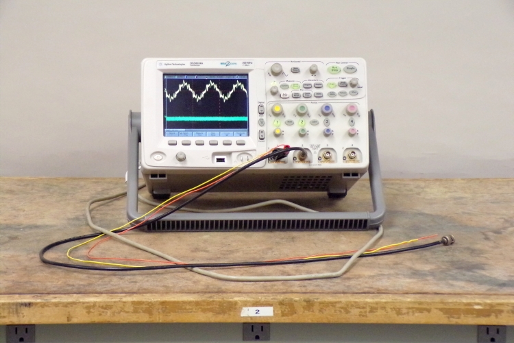
A pair of vinyl insulated wires (orange and yellow), about one meter long, is connected to channel 1 of the oscilloscope. A roughly equal length of coaxial cable (black) is connected to channel 2. Both are set near the (unshielded) line cord of the oscilloscope. The two oscilloscope traces show that the unshielded pair of wires is picking up 60-Hz noise from the line cord, whereas the shielded coaxial cable is not.
As several of the demonstrations in Chapter 72 -- Electromagnetic Induction and AC Circuits, show, an oscillating current produces an oscillating magnetic field, which induces an oscillating electromotive force in a nearby conductor. That is, it sets up an oscillating electric field over the length of the conductor. The current flowing in the line (“hot”) and neutral conductors in the AC line cord of the oscilloscope produces an oscillating magnetic field around each conductor. Since the current flows in opposite directions in the two conductors, it may seem odd that one could observe inductive pickup of noise from an AC line cord. In fact, if you use an inductive ammeter to see how much current is flowing in the line going to a device that is plugged into the wall, you must have a way of separating the hot and neutral lines in order to do this. If you close the clamp of the ammeter around the line cord, the oscillating magnetic flux from both the hot and the neutral lines passes through the clamp. This flux essentially cancels, and the ammeter reads zero current. A line splitter separates the hot and neutral lines so that you can close the ammeter clamp over either one alone. When you do this, you obtain a reading of the current flowing in the line. In contrast to the clamp closed around the line cord, a wire placed next to it is exposed to only a portion of the oscillating magnetic flux around the cord. Even though the oscillating magnetic flux from the hot and neutral conductors cancels, since there is a slight separation between the two conductors, there is not perfect overlap of the oscillating magnetic flux from them. Wherever the wire is near the line cord, then, it is likely for there to be some net oscillating magnetic flux, which induces an emf in the wire. Hence our ability to perform this demonstration in this way.
The oscilloscope trace for channel 1 (the pair of insulated wires) shows a 60-Hz oscillation with an amplitude on the order of 350 mV. The vertical scale is 100 mV per division. The trace for channel 2 (the coaxial cable), for which the vertical scale is 2 mV per division, is flat. (It shows random noise whose amplitude is about 1.5 mV.) A coaxial cable comprises a center conductor, a plastic insulator (dielectric) that surrounds the central conductor, a braided conductor that surrounds the insulator, and an outer coating of insulation. The braided outer conductor is woven so that it completely covers the dielectric and allows the cable to flex. The inner conductor thus sits within a cylindrical conductor, inside which the electric field (except for any introduced by the inner conductor) must be zero. The only electric field that influences the inner conductor is that produced by something that applies a potential difference between its two ends, for example, a power supply or an electronic instrument such as a signal generator. Thus, while an emf is induced in the pair of insulated wires placed near the AC line cord of the oscilloscope (actually, since the yellow wire is connected to ground, the emf we see is that in the orange wire), there is no emf induced in the center conductor of the coaxial cable similarly placed. The braided outer conductor acts as a shield (which is what it is usually called), preventing the induction of an emf by any oscillating magnetic fields that may be in the vicinity of the cable.
This is a consequence of Gauss’s law, according to which ΦE = q/ε0, where ΦE is the total electric flux through a closed hypothetical surface (called a Gaussian surface), and q is the charge enclosed by the surface. The flux is the integral of the electric field over the entire surface, or ΦE = ∮E · dS. Putting these together, we have ∮E · dS = q/ε0. Only charge enclosed by the surface contributes to the electric field inside it. Charge outside the surface does not. If we place the coaxial cable in an oscillating magnetic field, any change in the charge distribution as a result of an induced emf, affects only the outer surface of the shield, and the electric field inside it remains zero. The center conductor of the cable is thus shielded from noise that might be induced by nearby oscillating magnetic fields. This technique of shielding cables, either by making them coaxial or by wrapping the conductors in a foil sheath, finds wide application, especially in audio systems and electronic instrumentation.
References:
1) Halliday, David and Resnick, Robert. Physics, Part Two, Third Edition (New York: John Wiley and Sons, Inc., 1978), pp. 603-6.