 |
 |
|
 |
 |
|
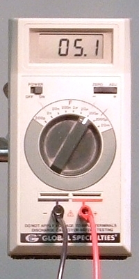
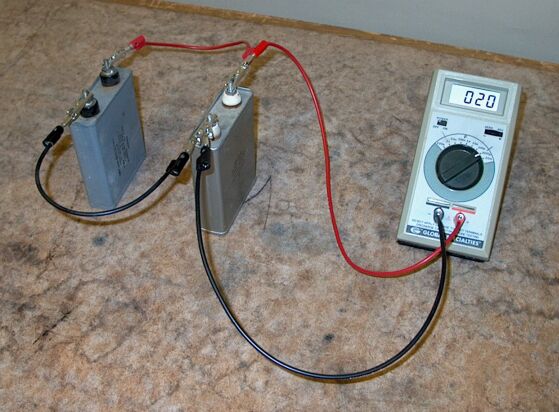
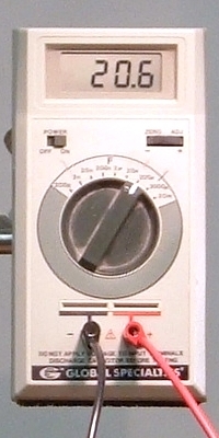
You can connect the two 10-microfarad capacitors in series, as in the top photograph, and in parallel, as in the bottom photograph. The capacitance meter shows the total (equivalant) capacitance. A camera connected to the data projector allows you to show the meter display to the class.
The pages for demonstrations 60.12 -- Separating charged parallel plates, and 60.15 -- Variable capacitor to capacitance meter, describe in some detail the relationship between a capacitor’s capacitance – the amount of charge it holds at a particular potential – and its geometry, and the page for demonstration 60.15 describes the action of a dielectric placed between the electrodes of a capacitor. Briefly, a capacitor is a device that has two electrodes, usually with a dielectric (insulator) between them. When one applies a voltage between the electrodes, equal and opposite charges appear on them; one electrode acquires a charge +q, and the other electrode acquires a charge -q. Though the net charge in the capacitor is zero, we refer to this process as charging the capacitor, and to the charge deposited on either plate as q. The relationship between the applied voltage and the charge delivered to the capacitor is
q = CV
where V is the applied voltage and C is the capacitance.
When you connect two or more capacitors together, their combination exhibits a capacitance that is different from that of any of the individual capacitors, and which depends on how they are connected. This demonstration shows the equivalent capacitances that result when you connect two capacitors of equal capacitance in series and in parallel. Each of the two capacitors has a capacitance of 10 μF.
The first photograph above shows the capacitors connected in series. As noted above, when you place a voltage across a capacitor, each plate acquires an equal and opposite charge to that of the other plate; one plate ends up with a charge of +q, and the other has a charge of -q. If two capacitors are connected in series, the plate that carries negative charge on one capacitor is connected to the plate that carries positive charge on the other capacitor. There cannot be a net charge on this pair of plates, since it had no net charge before the voltage was applied, and since the wire that connects them is not connected to anything else. Each plate thus carries equal charge of opposite sign. Also, whatever charge, +q, appears on the plate connected to the positive terminal of the power supply, an equal charge, -q, must appear on the plate connected to the negative terminal of the power supply. Thus, in a series combination, each plate carries a charge of ±q, and the charge in each capacitor is q. If we number the capacitors 1 and 2, we have
V1 = q/C1 and V2 = q/C2
Since the capacitors are in series, the voltage across the pair is the sum of the voltages across the individual capacitors, and
V = V1 + V2 = q[(1/C1) + (1/C2)]
C = q/V, so for the equivalent capacitance, we have
C = (1/[(1/C1) + (1/C2)]
and
1/C = (1/C1) + (1/C2)
We see that the capacitances of capacitors connected in series add reciprocally, and that the equivalent capacitance is smaller than the smallest capacitance in the combination. Since the two capacitors shown above have a capacitance of 10 µF, the equivalent capacitance of their combination in series is 1/C = [(1/10) + (1/10)], or 1/C = (1/5), or C = 5 μF, which is what the meter shows. We can extend this calculation to any number of capacitors connected in series.
The second photograph shows the two capacitors in parallel. In this arrangement, the voltage across both capacitors is the same. The charge, however, distributes itself on the capacitor plates according to the capacitances of the individual capacitors.
q1 = C1V and q2 = C2V
Since the total charge q on the capacitors is q1 + q2, we have
q = (C1 + C2)V
Again, C = q/V, and
C = C1 + C2
When capacitors are connected in parallel, their capacitances add directly. The two 10-μF capacitors connected in parallel together have a capacitance of C = 10 + 10 = 20, or C = 20 μF, which is what the meter shows. We can extend this calculation to any number of capacitors connected in parallel.
References:
1) Halliday, David and Resnick, Robert. Physics, Part Two, Third Edition (New York: John Wiley and Sons, 1978), pp. 654-655.
2) Sears, Francis Weston and Zemansky, Mark W. College Physics, Third Edition (Reading, Massachusetts: Addison-Wesley Publishing Company, Inc., 1960), pp. 519-521.