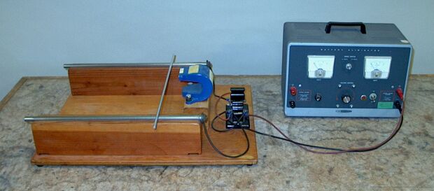
Mounted on the wooden platform at right in the photograph above, are a double-pole, double-throw switch, a U magnet set with its opening facing right with the north pole on top, and two 1/2-inch-diameter steel rods, or rails, set on either side of the magnet, extending to the right. Resting on the rails, perpendicular to them, is a 1/4-inch-diameter aluminum rod. With the DPDT switch flipped toward the back, as shown, when you turn the power supply on and then close the tap switch, the aluminum rod rolls into the magnet. If you then flip the DPDT switch toward the front and then close the tap switch, the aluminum rod rolls out of the magnet.
As is illustrated in demonstration 68.06 -- Fields of bar magnets, the field lines of the U magnet shown above run vertically from the north arm of the magnet (top) to the south arm of the magnet (bottom) between the two arms, and curve outward from the two poles (also running from north on top to south on the bottom), into the space between the two rails. In the plane in which the rails lie, in the center of the area between them, there is thus a magnetic field that points downward. An electric charge passing through a magnetic field experiences a (sideways) force, known as the Lorentz force, F = qv × B, where q is the magnitude of the charge, v is its velocity, and B is the magnetic field. The magnitude of the the force is qvB sin θ, where θ is the angle between v and B. When the charge is traveling parallel to the magnetic field, then, this force is zero, and when v is perpendicular to B, it is maximum (F = qvB). If the charge is part of a current, i, flowing in a wire, then the wire feels a force of F = il × B, where l is the length of the part of the wire that is in the magnetic field. If the wire is perpendicular to the magnetic field, this force is F = ilB.
As noted above, the rails are connected to a double-pole, double-throw switch, which is connected to a power supply, with the positive lead connected via a tap switch. With the DPDT switch flipped toward the back, as shown, the rear rail is connected to the negative terminal of the power supply, and closing the tap switch connects the front rail to the positive terminal. This causes current to flow in the aluminum rod resting on the rails, from the front rail toward the back rail. v, then, points toward the back of the table, and since B points downward, F = il × B points to the left (as does qv × B for a single charge traveling through the rod). This force directed toward the left causes the rod to roll along the rails toward the U magnet, and it rolls into the magnet.
If you now flip the DPDT switch to the opposite position, this exchanges the connections to the rails, so that when you now close the tap switch, current flows through the rod from the back rail to the front rail. F now points to the right, and the rod rolls out of the U magnet and continues along the rails.
The magnetic field diminishes in intensity with distance from the U magnet, so if you were to place the rod at just any spot along the rails, the force produced when you closed the tap switch might not be great enough to cause the aluminum rod to roll. For this reason, an arrow on the block that supports the back rail indicates the distance from which the rod will be sure to roll when you close the switch. It may be possible to set the rod somewhat farther from the magnet and still get it to roll, but from the indicated distance it should be certain to roll.
References:
- 1) David Halliday and Robert Resnick. Physics, Part Two, Third Edition (New York: John Wiley and Sons, Inc., 1978), pp. 718-22.
- 2) Berry, R. Stephen, Rice, Stuart A. and Ross, John. Physical Chemistry (New Your: John Wiley and Sons, 1980), p. 11.