 |
 |
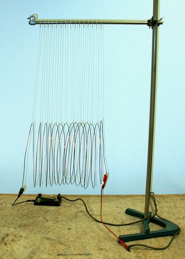
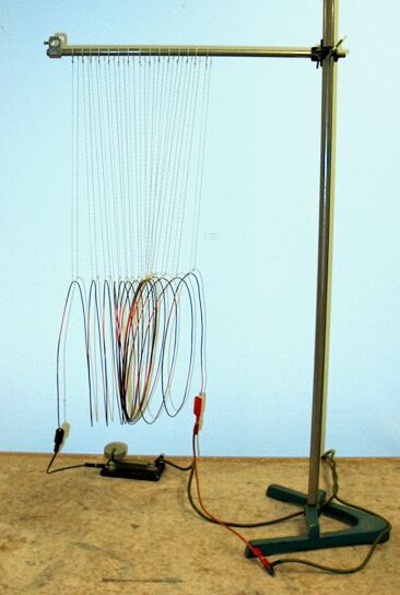
A suspended coil of wire is connected to a car battery in series with a tap switch. When you depress the switch, the magnetic field produced by the large current causes the coil to collapse (shown at right.)
As noted in the pages for demonstrations 68.15 – Compass and current-carrying wire, 68.18 – Compasses and current-carrying wire and 68.39 – Force between current-carrying wires, in 1820, Hans Christian Oersted – while performing a classroom demonstration! – discovered that a current in a wire produces a magnetic field around the wire. The relationship between this magnetic field and the current that produces it is given by Ampère’s law, which states ∮B · dl = μ0i, where dl is an element of a circular path around the wire, μ0 is the permeability constant, which equals 4π × 10-7 tesla·meter/ampere, and i is the current in the wire. By convention, current refers to the flow of positive charge, which is in the opposite direction to the flow of electrons. Evaluating the integral gives the magnitude of the magnetic field. ∮B · dl = (B)(2πr) = μ0i, or B = (μ0i/2πr). The right-hand rule (see demonstration 68.13 – Right-hand rule model) gives its direction. Place your right hand near the current-carrying wire, with the thumb pointing in the direction of the current. Now curl the fingers around the wire. Your fingertips point in the direction of the magnetic field (north). As also noted in the page for demonstration 68.13, the current flowing in a loop produces a magnetic field whose orientation is perpendicular to the plane of the loop, that is, a magnetic dipole with north on one side of the loop and south on the other side. If you curl the fingers of your right hand in the direction of the current flowing in the loop, and then extend your right thumb, your thumb points in the direction of the magnetic field (it points north). The central axis of the magnetic field lies along the central axis of the loop, normal to the plane of the loop. Thus, we have two equivalent ways of looking at this demonstration.
If we consider the magnetic field that surrounds each loop of the coil (circling the wire in the direction of the curled fingers of your right hand with your thumb pointing in the direction of the current), then the charges flowing in the neighboring loops of the coil experience a force Fq = qv × B, whose magnitude is Fq = qvB sin θ. Since the current in the wire is perpendicular to the magnetic field, θ = 90°. If we consider electron flow, q = e, and v = vd, the drift speed of the electron in the wire, and Fe = evdB. vd = j/ne, where j is the current density (i/A, where A is the cross-sectional area of the wire), and n is the number of conduction electrons per unit volume in the wire. Thus, Fe = jB/n. The length of wire in the field, l, contains nAl conduction electrons, so the total force on the wire is F = (nAl)Fe = nAl(jB/n). Since jA = i, this gives F = ilB.
As the coil sits in the photograph, current enters at the left end, flows clockwise through the coil (as viewed along its central axis from that end) and exits at the right end. The current flows in the same direction in each loop – upward in the back, and downward in the front. According to the right hand rule, as you follow the current around each loop, the tangent of the magnetic field around the wire points in toward the center of the loop on the left side, and radially outward on the right side. If we consider two neighboring loops, we find that the clockwise current in the left loop flowing through the inward-pointing magnetic field in the right loop, experiences a force F = il × B, which points to the right. (This holds over the entire circumference of the loop.) The clockwise current flowing in the right loop flowing through the outward-pointing magnetic field in the left loop, experiences a force F = il × B, which points to the left. The rightward force on the left loop and the leftward force on the right loop push the two loops together. This happens along the entire length of the coil. When you close the tap switch, then, the coil completely collapses, as shown in the photograph above at right. (The suspension isn’t quite uniform, so depending on exactly how the coil sits, the suspension can exert a torque that twists the axis of the coil. Still, the photograph clearly shows the strong attraction that draws all the loops of the coil together when you apply the current.)
This situation is identical to that of two parallel wires in which the current is flowing in the same direction. Reversing the current through the coil also reverses the direction of the magnetic field on each side of each loop, so the forces are the same as before, and when you apply current, the coil collapses.
As noted above, when current is flowing through the coil, each loop has a magnetic dipole moment, which we can express as μ = iA, where i is the current, and A is the area of the loop. (At the center of the loop, the magnetic field associated with this dipole is B = (μ0/2)(i/r), where r is the radius of the loop, and far from the loop (x >> r), B = (μ0/2π)(μ/x3), where x is the distance from the plane of the loop along the central axis.) With the current flowing clockwise from the left end of the coil to the right end, each coil has a magnetic dipole with north toward the right and south toward the left. The north end of the magnetic dipole of each loop is attracted to the south end of the magnetic dipole of the next loop (and its south pole is attracted to the north pole of the previous loop), and when you apply current, the coil collapses.
A fun fact:
Power transformers comprise tightly-wound coils that have many turns of wire, with no space between the turns. All the turns in each coil are, of course, wound in the same direction, so current flows through all of them in the same direction. A DC current would cause all the turns to be pulled together. The current flowing through a power transformer, however, is AC at the line frequency of 60 Hz. Every half cycle, the current reaches a maximum. Between maxima, the current decreases, passes through zero and increases again. This means that every half cycle, the coil turns are pulled together, and between half cycles, they relax. This is why, no matter how tightly wound they are, power transformers hum.
References:
1) Halliday, David and Resnick, Robert. Physics, Part Two, Third Edition (New York: John Wiley and Sons, 1977), pp. 677, 719, 721-2, 746-9, 758-62.
2) Sears, Francis Weston and Zemansky, Mark W. College Physics (Reading, Massachussetts: Addison-Wesley Publishing Company, Inc., 1960), pp. 641-9.