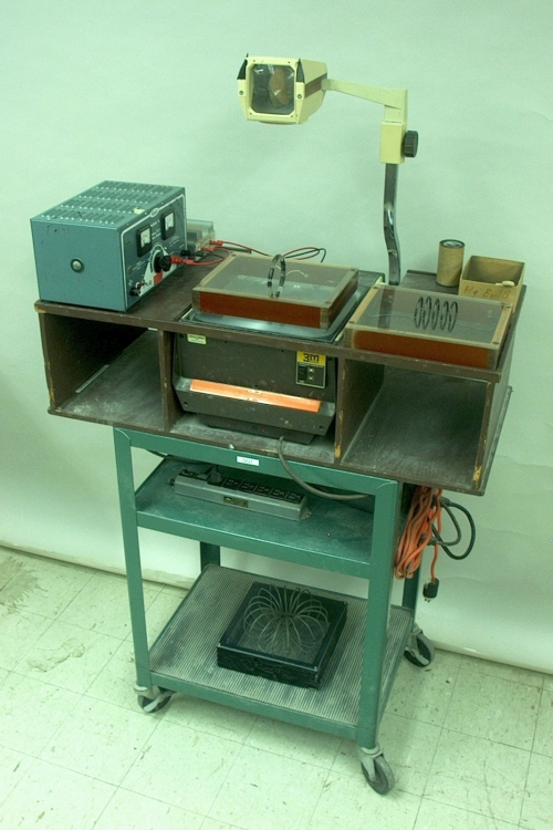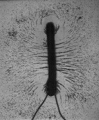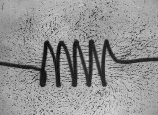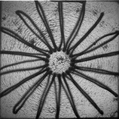
Wound through transparent plastic sheets mounted on frames, are a coil, a solenoid and a toroid. When you connect one of these to the power supply and turn it on, sprinkle iron filings onto the sheet, shake gently and set the apparatus on the overhead projector, you obtain one of the patterns shown below. (Since the sheet for the toroid sits higher than those for the coil and the solenoid, you will have to adjust the projector focus accordingly.)
Coil
Solenoid
Toroid
As noted in the pages for demonstrations 68.15 – Compass and current-carrying wire, 68.18 – Compasses and current-carrying wire and 68.39 – Force between current-carrying wires, in 1820, Hans Christian Oersted – while performing a classroom demonstration! – discovered that a current in a wire produces a magnetic field around the wire. The relationship between this magnetic field and the current that produces it is given by Ampère’s law, which states ∮B · dl = μ0i, where dl is an element of a circular path around the wire, μ0 is the permeability constant, which equals 4π × 10-7 tesla·meter/ampere, and i is the current in the wire. By convention, current refers to the flow of positive charge, which is in the opposite direction to the flow of electrons. Evaluating the integral gives the magnitude of the magnetic field. ∮B · dl = (B)(2πr) = μ0i, or B = (μ0i/2πr). The right-hand rule (see demonstration 68.13 – Right-hand rule model) gives its direction. Place your right hand near the current-carrying wire, with the thumb pointing in the direction of the current. Now curl the fingers around the wire. Your fingertips point in the direction of the magnetic field (north).
For a coil, the turns are close together, and the magnetic field produced by a current flowing through it resembles that produced by a similar current flowing in a single loop. At the center of the coil, the field is B = (μ0/2)(ni/r), where r is the radius of the coil, and n is the number of turns in the coil. In a solenoid, the turns are wound side by side to form a cylinder. For an ideal solenoid, its length is much, much greater than its diameter; it approaches infinity. The current in such a solenoid resembles a cylindrical sheet of infinite length. For points outside the sheet, B approaches zero. For a real solenoid whose length is much greater than its diameter, this is a reasonable approximation if we consider only external points that are not near the ends of the solenoid. We consider a rectangular path, l, that cuts several turns along one side of the solenoid, whose length parallel to the axis of the solenoid is h. Since B outside the cylinder equals zero, the integral along the outside edge of the path equals zero. The integral along the two ends of the path is zero, because these run perpendicular to the magnetic field lines. The integral along the section of the path inside the solenoid is Bh. (So ∮B · dl = Bh.) Since the path of integration encompasses several turns of the solenoid, the current through it is the current flowing through the solenoid, i0, multiplied by the number of turns, n, or i = i0n. Bh = μ0inh, and B = μ0in. We see that B is independent of the radius of the solenoid, so the magnetic field inside the solenoid is uniform (except for deviations near the ends).
A toroid is essentially a solenoid bent into the shape of a doughnut. Because the two sides of the coil now have different lengths – the inner and outer radius of the toroid – but the same number of turns, the integral ∮B · dl = μ0i becomes (B)(2πr) = μ0i0n, where i0 is the current flowing through the toroid, and n is the number of turns in the toroid. Rearranging this, we have B = (μ0/2π)(i0n/r). We see that the magnetic field inside the toroid increases as we go from the outer radius to the inner radius. This makes sense, because the number of turns per unit length (and thus the current per unit length) is greater on the inside than on the outside.
As demonstrations 68.15 and 18.18 show, the needle of a compass placed near a current-carrying wire, aligns itself so that it is tangent to the magnetic field, pointing in the same direction as the field. Similarly, iron filings placed in a magnetic field align with it. (If they are not already magnetized, they become so under the influence of the field, and align with it.) If friction prevents them from doing so, gently shaking the surface on which they lie reduces the effect of friction and allows the filings to align with the field in loose chains that follow the lines of magnetic flux. The magnetic flux is, essentially, the density of the magnetic field passing through a particular surface, and is expressed by the integral ΦB = ∫B · dS.
The SI unit of magnetic field, B, is the tesla (T; 1 tesla = 1 weber/meter2), and the SI unit of magnetic flux, Φ, is the weber (Wb; 1 weber = 1 N · m/A = 1 J/A).
References:
1) Halliday, David and Resnick, Robert. Physics, Part Two, Third Edition (New York: John Wiley and Sons, 1977), pp. 720, 746-9, 755-8.


