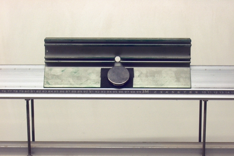
An air track glider with a magnet attached to each side rapidly slows down because of eddy currents induced in the track.
The glider in the photograph above has attached to it on each side a rare-earth disc magnet. Each magnet is attached with Velcro® so that you can easily remove and replace it. To show that the glider glides freely even when loaded with the weight of the magnets, you can set them on top of the glider, one at each end, and then send the glider down the air track. (There is a patch of Velcro® at each end on top of the glider. These were added after this photograph was taken.) With the magnets set on either side as shown in the photograph, give the glider a push down the air track, and it quickly slows to a stop.
Each magnet attached to the glider is a disc magnet, polarized through its thickness. That is, one face is north and the other face is south, so that near each face, the field lines run perpendicular to the surface and thus extend perpendicularly through the glider and the surface of the air track. As the glider travels down the track, the moving magnetic field induces an EMF in the track in the area underneath the magnet, which causes (positive) charges within this area to flow along a vertical path. Depending on the direction in which you set the glider moving, and the direction of the magnetic field lines, the charges flow upward or downward along this path. The regions to either side of the magnetic field provide return paths for these moving charges, and this produces two sets of currents, one on either side of the magnet, which circulate in opposite directions. For example, assume that the magnet in the photograph has its north pole facing outward. The magnetic field lines point outward through the surface of the air track. If you push the glider to the left, the EMF induced by the moving field causes current to flow downward. (Relative to the magnetic field, the charges are moving to the right, and they experience a force, F = qv × B, which points down.) This produces a set of currents in front of the magnet (on the left) that flow clockwise, and a set of currents behind the magnet (on the right) that flow counterclockwise. The same thing happens under the magnet on the opposite side of the glider. Such currents induced in an extended object (as opposed to a ring or a loop of wire) are called eddy currents.
The downward-flowing charges in the region of the magnetic field experience a force, F = qv × B, which points to the left. Since the charges in the currents on either side of the magnetic field are outside the field, they do not experience such forces, and there is a net leftward force. Relative to the (leftward-moving) glider, the rail of the air track is moving to the right. This leftward force thus opposes this motion and slows the glider. A device such as this, in which eddy currents slow a moving part, is known as an eddy current brake, hence the title of this demonstration. Such devices find practical use in certain vehicles, exercise equipment, and in industry. For some examples, see Eddy current brake on Wikipedia, and 5 Applications of Eddy Current Brakes on the head rush technologies web site.
In connection with oscillating systems, this phenomenon is also known as eddy current damping or magnetic damping. In this context it is perhaps most commonly used in mechanical balances, in which an aluminum vane attached to the end of the beam rides within a slot in the vertical member that holds the zero indicator. Magnets on either side of the slot induce eddy currents in the vane as the beam oscillates up and down, which slows the oscillation and reduces its amplitude so that the beam comes to rest more quickly than it otherwise would.
References:
1) Sears, Francis Weston and Zemansky, Mark W. College Physics, Third Edition (Reading, Massachusetts: Addison-Wesley Publishing Company, 1960) p. 672-3.
2) Halliday, David and Resnick, Robert. Physics, Part Two, Third Edition (New York: John Wiley and Sons, 1977), pp. 787, 791.