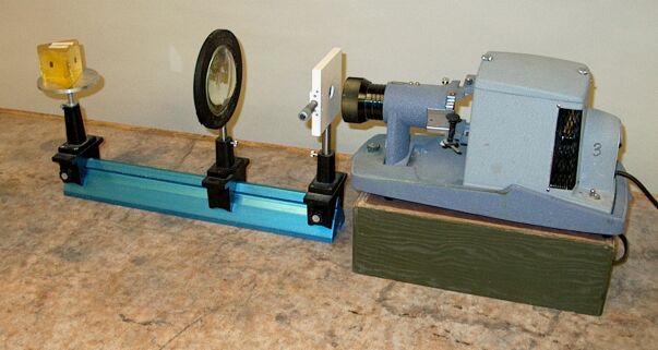
The light from a projector passes through a slit and lens to a prism. The prism disperses the light to project the visible spectrum onto a screen.
As is illustrated by demonstration 80.18 -- Refraction tank, when light passes from one medium into another medium whose density is different from that of the first, it speeds up or slows down, depending on whether the second medium is less dense or more dense, respectively, than the first. As a result, except if it crosses the boundary between the two mediums at a zero angle of incidence, the light is bent, or refracted, the angle of refraction depending on the angle of incidence and the ratio of the indices of refraction of the two media as expressed by Snell’s law:
n1 sin θ1 = n2 sin θ2
The index of refraction of a material is the ratio of the speed of light in a vacuum to that in the material. (The speed of light in air at 1 atm and 20°C is close enough to that in vacuum that the index of refraction is 1.0003.) The index of refraction of a material depends on the wavelength of the light passing through it. As Newton put it in Proposition I, Theory I in Opticks, Lights which differ in Colour, differ also in Degrees of Refrangibility. Following this statement, he describes an experiment in which he observed that the two halves of a stripe, one blue and one red, appeared at different heights when he viewed them through a prism. He further states in Proposition II, Theory II, The Light of the Sun consists of Rays differentially Refrangible. He then describes an experiment in which he observed that the spot produced by the rays of the sun passing through a hole in a window shutter, refracted by a prism, produced an elongated colored spot on a wall, red at its least refracted end and violet at its most refracted end, with yellow, green and blue between them. In this demonstration, the hot filament of a projector lamp takes the place of the sun, and the slit and lens function as the hole in the window shutter. Also, the prism is turned so that it refracts the light horizontally instead of vertically. With the apparatus set as shown in the photograph, the spectrum appears on a screen placed some distance from the right end of the table, with the red end on the right, and the blue end on the left.
This phenomenon in which a material refracts lights of different wavelengths at different angles, is called dispersion. Both the index of refraction how it varies with the wavelength of incident light are intrinisic properties of the particular material. By measuring the degree to which a material refracts light of various wavelengths, one can at least roughly quantify the dispersion associated with the material. For materials that are transparent in the range of the visible spectrum, optics manufacturers use light of wavelengths that correspond to three of the Fraunhofer lines – dark lines in the solar spectrum that Joseph Fraunhofer observed and studied. Though there is some variation in the choice of lines, the most commonly used wavelengths are the C line at 6,563 Å (red, from an H atom transition), the D2 line at 5,890 Å (yellow, one of the sodium D lines) and the F line at 4,861 Å (blue, from an H atom transition).
We now wish to compare the dispersion of the rays from the C and F lines to the deviation of the ray from the D2 line. For small angles, Snell’s law becomes n1θ1 = n2θ2, or θ1/θ2 = n2/n1. Differentiating and using subscripts C, D and F for the three lines, we find that the dispersion of the C and F rays, θ2, F - θ2, C, is proportional to n2, F - n2, C. The deviation of the D2 ray, θ1 - θD, is proportional to nD - 1. As an example, we will use indices of refraction that are typical for crown glass, which for these three wavelengths are nC = 1.5244, nD = 1.5270 and nF = 1.5330. For this glass, then, the dispersion of the C and F rays is proportional to 1.5330 - 1.5244 = 0.0086, and the deviation of the D2 ray is proportional to 1.5270 - 1 = 0.5270. We see that the deviation of the yellow ray is just over 60 times the dispersion of the blue and red rays. The dispersive power of a material is the ratio of the dispersion of the C and F rays, and the deviation of the D2 ray, or:
(1/ν) = (nF - nC)/(nD - 1)
The reciprocal of the dispersive power, ν, also called the Abbe number, after Ernst Abbe (and also sometimes called the constringence and also sometimes designated V or Vd),
ν = (nD - 1)/(nF - nC),
typically lies between 30 and 60 for optical glasses.
Depending on the situation, dispersion in an optical material can either pose a disadvantage or be used to advantage. For example, in lenses, dispersion causes the focal length to vary with wavelength, which results in colored fringes around the edges of images. This is called chromatic aberration. One can correct this by the use of an achromat – a converging lens made of one type of glass, in contact with a diverging lens made of a different type of glass. Since the dispersive powers of the two glasses differ, it is possible to design the pair so that the dispersion of the diverging lens cancels that of the converging lens, and together they have the desired focal length, with essentially no dispersion.
On the other hand, if one wishes to analyze the components of polychromatic light, for example the light from a discharge tube containing an element of interest, one can separate the various emission lines by passing the light through a prism.
Though there are exceptions, the index of refraction generally increases with the density of the material, and the dispersion does as well. If we plot the index of refraction vs. wavelength, we find that the index of refraction increases as the wavelength decreases (the deviation of violet light is greater than that of red light), and that the rate of increase (dn/dλ) becomes greater at shorter wavelengths (so the violet end of the spectrum is more greatly spread out than the red end of the spectrum). Usually, as noted above, for different materials, for light near a given wavelength, the curve is steeper for the material with the greater index of refraction.
Though the dispersion curves of various materials share the properties described above, the curve for each material is unique, and there is no simple way to relate the curve for one substance to that of another. For this reason, the dispersion of different substances is said to be irrational. Still, for a given substance it is possible to describe this curve mathematically. This was first done successfully by Cauchy in 1836, whose equation may be written
n = A + B/λ2 + C/λ4,
where A, B and C are constants whose values depend on the particular material. Measuring n at three different wavelengths yields three equations, which one can then solve to find A, B and C. In many cases, the equation with only the first two terms yields sufficient accuracy:
n = A + B/λ2
To find A and B, one needs to measure n at only two wavelengths. Differentiating this gives
dn/dλ = -2B/λ3.
To perform spectroscopy, one passes the light from the source through a slit and collimating lens to the prism, and views the light deflected by the prism by means of a telescope. As one rotates the telescope about the central axis of the instrument, one observes colored lines (images of the slit) at various positions. (These positions are marked in degrees on a goniometer on the plate that supports the collimator and telescope, a vernier scale on which shows the position of the telescope. The precise location of a line is determined by means of a cross hair in the telescope, which one centers on the line.) Since the slit is extended in the direction perpendicular to the plane in which the axes of the collimator and telescope lie, some of the light does not travel parallel to this plane, and thus does not pass through the prism in a principal section. Because they take a longer path through the prism, these off-axis rays are deviated more greatly than those that pass through a principal section, which causes the image of the slit to be curved. (It is concave toward the short-wavelength end of the spectrum.) This distortion is minimized when one sets the prism at the position relative to the incident beam where it produces the minimum deviation. This occurs when the angle at which the beam exits the prism is equal to the angle of incidence of the beam as it enters the prism.
The angular dispersion of the prism is
dθ/dλ = (dθ/dn)(dn/dλ)
At minimum deviation the beam traverses the prism parallel to its base, and if t1 is the distance the beam travels near the apex and t2 is the distance it travels near the base, then dθ/dn = (t2 - t1)/a, where a is the width of the exiting beam. If the beam covers the face on which it is incident, this reduces to dθ/dn = t/a, where t is the length of the base of the prism. The angular dispersion is thus
dθ/dλ = -(2t/a)(B/λ3).
References:
- 1) Newton, Sir Isaac. OPTICKS or A Treatise of the Reflections, Refractoins, Inflections & Colours of Light (Mineola, New York: Dover Publications, Inc., 1979).
- 2) Jenkins, Francis A., and White, Harvey E. Fundamentals of Optics (New York: McGraw-Hill Book Company, Inc., 1950), pp. 13-14, 26, 462-466.
- 3) Longhurst, R. S. Geometrical and Physical Optics, Second Edition (New York, N.Y.: John Wiley and Sons, Inc., 1967), pp. 75-76.