A video of this demonstration is available at this link.
You can use the He-Ne laser shown above with a variety of single slits, double slits, multiple slits, circular apertures and opaque points, to show diffraction and interference. (The laser emits light whose wavelength is 632.8 nm.) Also available is a set of three transmission gratings that have different groove spacings, and a set of single slits that are taped to make rectangular apertures that have different aspect ratios, and circular apertures. A flashlight (not shown) allows you to see in the dark which particular slit, or slits, you have aligned with the laser beam.
When light passes near an edge, it is bent; it spreads out as it passes the edge. This is called diffraction. Normally we do not notice this phenomenon, but when light passes through apertures whose dimensions begin to approach the wavelength of the light passing through them, it becomes quite important. Also, diffraction effects are normally less apparent than they might otherwise be, because most light sources are extended, so light from various parts of a source produces overlapping diffraction patterns, and because most light sources are not monochromatic, which gives rise to overlapping patterns from light of different wavelengths. (The diffraction is wavelength dependent; vide infra.) A related phenomenon, which occurs when light passes through two or more (parallel) slits, is called interference. Diffracted light projected onto a screen produces a pattern of light and dark regions, the nature of which depends on the wavelength of the light and the geometry of the system. Light that passes through double or multiple slits undergoes both diffraction and interference. When this light is projected onto a screen, it produces a pattern that is a combination of the two patterns produced by diffraction and interference. It is common to cover interference before diffraction. Because it is impossible to observe interference without diffraction, however, and because it is simpler to start with single slits, diffraction appears first on this page. Since the light source for this demonstration is a laser, the light incident on the slit sets constitutes plane waves. The slit widths and spacings are exceedingly small compared to the distance between the slits and the screen, so the distance between the slits and the screen is effectively infinite. Light coming from the source to any part of the slit, and light arriving at a particular point on the screen from any part of the slit, travels at the same angle with respect to the plane in which the slit lies. The diffraction we observe under these conditions is often referred to as Fraunhofer diffraction.
Monochromatic light of wavelength λ passing through a slit whose width is a, falls on a screen placed at a distance D from the slit. Light passing straight through the slit is incident on the screen at an angle of 0°. (The slit lies on a plane parallel to the screen.) Light rays passing through different parts of the slit to fall at a particular point P on the screen, a distance y from the center, travel different distances to arrive there. In order for there to be an intensity minimum at that point, the path difference for pairs of rays meeting at that point must equal one half wavelength. For example, consider a ray coming from one side of the slit, and one coming from the middle of the slit, a/2 away. If D ≫ y, then this path difference, λ/2, divided by a/2, equals sin θ; (a/2) sin θ = λ/2, or a sin θ = λ. Every ray coming from the first half of the slit has another ray coming from the other half (a/2 away from it) that cancels it at the screen. Similarly, if we consider rays coming from points a/4 apart, we find that (a/4) sin θ = λ/2, or a sin θ = 2λ. This leads to the general formula for the locations of the minima in the diffraction pattern:
a sin θ = mλ, where m = 1, 2, 3, . . .
Also, if D ≫ y, then sin θ ≈ tan θ ≈ y/D, and ay/D = mλ (or y = mλD/a; m = 1, 2, 3, . . .). Roughly in the middle of each pair of adjacent minima is an intensity maximum. Further analysis shows that the phase difference (in radians) between a ray coming from one edge of the slit and a ray coming from the other edge is
φ = (2π/λ)(a sin θ),
and the amplitude and intensity are, respectively
Eθ = Em (sin α)/α, and
Iθ = Im [(sin α)/α]2, where
α = (1/2)φ = (πa/λ) sin θ. The subscript m refers to the center of the diffraction pattern, and the subscript θ refers to the angular displacement of a point from the center.
Below are some sample (single-slit) diffraction patterns. For reference, the wavelength of the light produced by the laser in this demonstration is 632.8 nm.
1) The pattern from a variable slit, starting with the slit wide enough to allow the beam through unobstructed, then narrower and narrower, until it is as narrow as possible while still allowing enough light through to make a clear pattern:
2) Patterns from four single slits, in order of decreasing width:
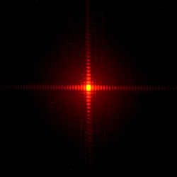
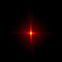
160 μm 80 μm 40 μm 20 μm We see from these patterns that as the equations would indicate, the narrower the slit, the broader the diffraction pattern; halving the slit width doubles the breadth of the diffraction pattern. All of these slits, of course, are much taller than they are wide. Also available is a set of single slits whose widths are 0.12 mm, 0.24 mm and 0.48 mm, taped over to make rectangular apertures that have different aspect ratios. The diffraction patterns they make are below.
Taller than Wide
Width and Height Almost Equal
Wider than Tall
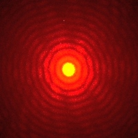
If we bend the edge around which the light is diffracted, into a circle (a small, circular hole), the diffraction pattern curves around on itself to produce rings, as in the images below.
0.48-mm Diameter
0.24-mm Diameter
0.12-mm Diameter
0.08-mm Diameter
As noted above, when light passes through two slits, it undergoes both diffraction and interference. We consider a pair of slits, whose width is a, and for which the separation between them is d, set at a distance D from a screen. (The plane in which the pair of slits lies is parallel to the screen.) Except for the light traveling from the slits to the center of the screen, to reach a particular point on the screen, the light from one slit must travel a different distance from that traveled by the light from the other slit. If D ≫ d, then this path difference equals d sin θ. In order for there to be an intensity maximum at the screen, the path difference must equal an integral number of wavelengths of the light, or
d sin θ = mλ, where m = 1, 2, 3, . . .
At the center of the screen is a central maximum, which corresponds to m = 0. For each maximum given by the equation above, another appears on the opposite side of the central maximum, an equal distance away from it. (That is, m = -1, -2, -3, . . .) To find the locations of the intensity minima, we note that the path difference must equal some half-integral number of wavelengths, or
d sin θ = (m + 1/2)λ m = 1, 2, 3, . . . (minima).
Also, if D ≫ y, then sin θ ≈ tan θ ≈ y/D, and dy/D = mλ (or y = mλD/d; m = 1, 2, 3, . . .). Further analysis shows that the phase difference (in radians) between the light coming from one slit and that coming from the other slit is
φ = (2π/λ)(d sin θ),
and that the amplitude and intensity are, respectively
Eθ = Em cos β, and
Iθ = Im cos2 β, where
β = (1/2)φ = (πd/λ) sin θ. The subscript m refers to the center of the diffraction pattern, and the subscript θ refers to the angular displacement of a point from the center. These equations apply only for narrow slits, that is a ≪ λ. In this situation, the intensity in the central diffraction maximum from each slit is spread evenly across the screen, so that all the interference maxima have the same intensity. For visible light, unless the slits are exceedingly narrow, this condition is not usually met, and it is far from being met for the slits used in this demonstration. As a result, the diffraction causes a variation of intensity among the interference maxima, without changing their positions. If we use the subscripts “int” for interference and “dif” for diffraction, we have from the above that
Iθ, int = Im, int cos2 β and Iθ, dif = Im, dif [(sin α)/α]2, where
β = (πd/λ) sin θ and α = (πa/λ) sin θ. Putting these together, for the expression for intensity that includes both interference and diffraction, we have
Iθ = Im (cos β)2 [(sin α)/α]2,
where β and α are as above. This equation shows that the intensities of the interference peaks vary according to the diffraction pattern. We say that the interference pattern is modulated by the diffraction pattern.
Below are some sample (double-slit) diffraction patterns. Again, the laser wavelength is 632.8 nm.
Pairs of 80-μm-Wide Slits
500 μm
Separation250 μm
SeparationPairs of 40-μ-Wide Slits
500 μm
Separation250 μm
SeparationFrom these patterns we see that as the equations would indicate, the smaller the slit separation, the greater the distance between interference maxima; halving the slit separation doubles the spacing among interference maxima. We also observe for each pattern, a variation of the intensity of the interference maxima, which corresponds to that of the broader diffraction pattern. For a given slit width, halving the slit separation halves the number of interference maxima that fall within a particular diffraction maximum, and for a given slit separation, halving the slit width doubles the number of interference maxima that fall within a particular diffraction maximum.
Also available is a set of slits grouped in different numbers. Each slit has a width of 40 microns, and the spacings for all of them are 0.125 mm. Below is the set of patterns they give.
Two
SlitsThree
SlitsFour
SlitsFive
SlitsWe see that as the number of slits increases, the variation in intensity caused by diffraction decreases, and the intensity in the interference maxima comes closer to being uniform across the pattern. The behavior begins to resemble that of a diffraction grating, which is a device made of many closely-spaced parallel slits (or grooves). (See demonstration 84.18 – Laser beam diffracted by reflection gratings.) A set of transmission gratings (rightmost in the photograph), whose groove densities are 100, 300 and 600 grooves/mm, is also available.
References:
1) Halliday, David and Resnick, Robert. Physics, Part Two, Third Edition (New York: John Wiley and Sons, 1977), pp. 994-7, 1002-3, 1025-32, 1037.
2) http://hyperphysics.phy-astr.gsu.edu/hbase/phyopt/sinslit.html#c1 and links to related topics.
3) http://hyperphysics.phy-astr.gsu.edu/hbase/phyopt/slits.html#c1 and links to related topics.
4) Jenkins, Francis A. and White, Harvey E. Fundamentals of Optics, Second Edition (New York: McGraw-Hill Book Company, Inc., 1950). Chapter 15 gives a thorough treatment of single-slit diffraction, and chapter 16 gives a thorough treatment of double-slit diffraction. (Chapter 17 covers diffraction gratings.)
5) Crawford, Jr., Frank S. Waves; Berkeley Physics Course – Volume 3 (San Francisco: McGraw-Hill Book Company, Inc., 1968), p 488.


