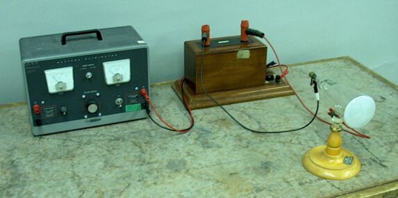

An induction coil driven by a (DC) power supply provides the high voltage required to produce cathode rays in a partially evacuated glass tube. When these rays arrive at the phosphor-coated face of the tube, they cause it to emit a green glow. An aluminum Maltese cross sits on a pivot inside the tube. When you tilt the tube to set the cross upright, it casts a shadow on the phosphorescent screen. Please note: This demonstration may generate a significant quantity of x-rays. Have the power on only for a short time, and keep a safe distance from the apparatus while it is running.
The tube shown above is a Crookes tube, after William Crookes, one of the people who invented it in the mid-19th century. (Another person who experimented with these tubes was Johann Hittorf, which is why they are also sometimes called “Crookes-Hittorf” tubes.) At the bottom of the tube, in the stem that supports it in the wooden stand, is an electrode to which the positive terminal of the induction coil is connected, the anode. At the rear of the tube is a plate, the cathode, to which the negative terminal of the induction coil is connected. The tube is evacuated to a pressure that is high enough to allow for electrical breakdown of the gas inside, but low enough that electrons ejected from the cathode via collisions of positive ions with it, may reach the front surface of the tube. This process is called secondary emission, and is what forms the beam of electrons that flow from the cathode to the front of the tube. These electrons are called cathode rays. In cathode ray tubes used in older televisions, computer displays and oscilloscopes, the electrons are emitted from a heated cathode, and focused electrostatically to form a spot, which is then steered electrostatically (and sometimes also electromagnetically) to produced the desired display. The cathode rays produced in the tube used in this demonstration form a broad, unfocused beam.
In experimenting with similar tubes, Crookes and others observed under certain conditions a greenish glow emanating from the glass envelope of the tube itself. (The exact color depended on the type of glass from which the tube was made.) They were able to determine that this glow was not from the excited gas within the tube, but from rays traveling from the cathode to strike the glass envelope, which caused phosphorescence in the glass. At the time, they thought that these rays were negatively charged molecules. In 1895, Jean Baptiste Perrin confirmed that cathode rays were indeed negative. In 1897, J.J. Thomson performed experiments with a tube that was modified so that he could produce a well defined beam of cathode rays, and so that he could deflect them by means of an electric field and also by means of a magnetic field. Through these experiments Thomson again confirmed that cathode rays were negative, but in addition was able to determine the charge-to-mass ratio, e/m, of the particles that composed them, and found it to be on the order of 2,000 times less than that of the lightest known atom (hydrogen). This constituted the discovery of what we now call the electron, and showed that cathode rays are streams of electrons. In order to make the places where cathode rays strike the glass envelope of the tube more clearly visible, manufacturers coat the face of the tube with a phosphor, which glows where the cathode rays strike it.
As noted above, and as we can see in the photograph above on the left, the tube used in this demonstration has inside it a metal plate in the shape of a Maltese cross, which sits on a pivot. If you tilt the tube back (face upward), the cross falls and lies horizontal at the bottom of the tube. The cathode rays then land over the entire surface of the front of the tube, causing the entire face of the tube to glow. If you tilt the tube forward (face downward), the cross now flips to the vertical position, and when you set the tube down and turn on the induction coil, the cross blocks the cathode rays that strike it on their way to the front of the tube, creating a shadow that is the same shape as the cross, as shown in the photograph above on the right.
References:
1) Crookes, William. Philosophical Transactions of the Royal Society of London 170(170) (1879), 135-164.
2) https://history.aip.org/exhibits/electron/jj1897.htm.
3) Tipler, Paul A. Foundations of Modern Physics (New York: Worth Publishers, Inc., 1969), pp. 113-116.
4) Halliday, David and Resnick, Robert. Physics, Part Two (New York: John Wiley & Sons, Inc., 1978), pp. 736-737.