

A video of this demonstration is available at this link.
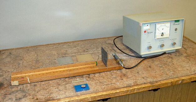
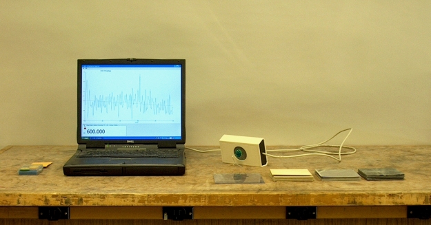
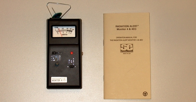
We have three radiation counters, all of which use a Geiger-Müller tube as a detector. In the top photo is a Nuclear-Chicago model 1613A, the middle photo shows a Black Cat Systems model GM-45, and at bottom is a Radiation Alert® Monitor 4 by S.E. International. Below is a short description of the three major nuclear decay processes, a list of available radiation sources and their modes of decay, a note on how a Geiger-Müller tube works, some details regarding the instruments shown above, and some notes on setting up the demonstration.
There are three types of nuclear decay:
1) α decay is the spontaneous emission of an α particle by a nucleus that has a large atomic number, Z. (An α particle is a helium nucleus, 2He4(2+).) This is a common process for nuclei having Z greater than 82. Schematically, the decay is ZAA → Z-2BA-4 + 2He4(2+). (Z is the atomic number, which is the number of protons in the nucleus, and A is the mass number, which is the total number of protons and neutrons in the nucleus.)
2) β decay is the spontaneous emission of a (negatively charged) electron. In this process, a nucleus having a particular Z and A changes to one having Z + 1, A. That is, the number of protons increases by one, the number of neutrons decreases by one and the total number of protons and neutrons remains constant.
β decay can also occur in two other ways, which are electron capture and positron emission. In both these cases, Z decreases by one, the number of neutrons increases by one and A remains constant. In electron capture, the nucleus captures a (negatively charged) atomic electron. In positron emission, the nucleus emits a positron, which is the positively charged antiparticle that corresponds to an electron.
Positron emission is used in the medical scanning method called positron emission tomography, or PET. In this technique, the patient is given a dose of a radioisotope-labeled molecule, usually a sugar, water or ammonia, or a molecule that binds to a particular receptor of interest. When the ingested molecules get to their target tissues, the PET scan is performed. The positrons emitted by the radioisotopes travel a short distance (up to a few millimeters) before they encounter electrons and undergo pair annihilation with them. When an electron and a positron undergo annihilation, a pair of γ rays, traveling in opposite directions, is emitted. These pairs of γ rays travel out of the patient and into scintillation detectors. Based on the placement and response of the detectors, a computer takes the resulting pulses and constructs an image of the tissues where the radioisotope-labeled molecule has concentrated. Examples of isotopes used as labels are 6C11, 7N13, 8O15 and 9F18.
3) γ decay is the emission of a high-energy photon (greater than ~10-3 MeV, or ~1 keV) that occurs when a nucleus decays from an excited state to a lower-energy state.
α particles, being the largest and also the most highly charged of the above particles, interact strongly with matter, and thus cannot penetrate to any significant depth. One can stop them with a piece of paper, skin can stop them, and they cannot travel more than a few centimeters in air. β particles, since they are small and carry a single charge, penetrate a moderate distance (~1 cm in human tissue). γ rays carry no charge and are highly penetrating.
Radiation sources:
For this demonstration, we have several radioactive sources:
1) Shown above in the middle and bottom photographs is a piece of depression glass, also known as “vaseline” glass. This glass contains small amounts of uranium oxide (used for color). Uranium’s primary decay mode (77%) is α emission:
92U238 → 90Th234 + 2He4(2+) (4.195 MeV)
(The other mode of decay, is spontaneous fission, 23%. The half-life is 4.51 × 10⁹ y.)
2) 38Sr90 source, half-life 28.1 y, originally 0.1 μCi (1 curie (Ci) = 3.7 × 10¹⁰ disintegrations/s) (at this writing, 9/22/08, perhaps ~1/5 half-life old): This is a β emitter:
38Sr90 → 39Y90 + β (0.546 MeV, 100%) + antineutrino
3) 82Pb210 source, half-life 21 y, originally 0.1 μCi (at this writing, 9/22/08, perhaps about 1/4 half-life old): This is also a β emitter:
82Pb210 → 83Bi210 + β (0.015 MeV, 81%) + antineutrino
(The other 19% is α emission (0.061 MeV.)
4) 27Co60 source, half-life 5.26 y, originally 1.0 μCi (at this writing, 9/22/08, about one half-life old): This is a γ emitter:
27Co60 → 28Ni*60 + β(0.31 MeV); 28Ni*60 → 28Ni*60 + γ (1.17 MeV); 28Ni*60 → 28Ni60 + γ (1.33 MeV)
5) A pair of silk lantern mantles. These contain thorium in the form of its nitrate salt. 90Th232, the naturally occurring isotope of thorium, which has a half-life of 1.41 × 10¹⁰ years, decays by α emission to 88Ra228. (This decay to 88Ra228, which has a half-life of 5.8 years, begins a chain of further α and β decays, some with accompanying γ emission, that ends at 82Pb208, which is stable.) When it is heated to incandescence, thorium has particularly good emissivity, and thus improves the color and brightness of lantern light. While thorium-containing mantles pose no significant health risk if they are properly handled, because of thorium’s radioacitivity and that of its daughter nuclides, manufacturers of lantern mantles have begun to use other elements instead, and the use of thorium in lantern mantles is not as common as it used to be.
Geiger-Müller tube:
All three instruments shown above use a type of Geiger-Müller tube as a detector. This is a device that is filled with an inert gas, usually one of the noble gases (He, Ne, Kr or Ar, usually Ar or Ne), at a pressure of a few tenths of an atmosphere, and which has an anode at its center and a cathode surrounding the outside. Depending on the geometry, the cathode may have an opening to allow radiation through. In some cases, the cathode is a thin conductive coating that is essentially transparent to incoming radiation. As shown in the equations above, the particles emitted in radioactive decay emerge with energies that range from a few keV to several MeV, and so are capable of ionizing anything they encounter. When such a particle enters a Geiger-Müller tube, it ionizes a few atoms of the fill gas. The resulting electrons are accelerated toward the anode by the high voltage placed between it and the cathode. As they are accelerated, they acquire enough energy to ionize more atoms of the gas, causing an avalanche, which produces a pulse of current that the instrument registers as a disintigration. Since the ions are much heavier than the electrons, they accumulate around the anode, temporarily collapsing the electric field around it and thus stopping the discharge. The positive ions then travel toward the cathode. On their way, they are neutralized via charge exchange with a “quenching” gas, a small amount of which is mixed with the fill gas. This prevents the production of a second pulse from the energy released by the neutralization of the ions. The quenching gas can be either a halogen such as chlorine or bromine, or a small, organic molecule such as butane or ethanol.
The Nuclear-Chicago instrument uses a Raytheon CK-1021 Geiger-Müller tube, which has a glass envelope whose thickness is 35 mg/cm2. (Assuming the density of the glass is about 2.25 g/cm3, this corresponds to a thickness of 160 μ.) It can detect β and γ radiation only.
The Geiger-Müller tubes in the GM-45 and Monitor 4 have a mica window of 1.75 mg/cm2 (1.5-2.0 mg/cm2 for the Monitor 4), which corresponds to a thickness of about 6 μ. This is thin enough to allow detection of α particles having energies of about 3 MeV or greater.
There is some γ radiation associated with the decay of 92U238 and of 82Pb210, so you may obtain some counts above background with these samples on the Nuclear-Chicago instrument.
Operation of the instruments:
1) Nuclear-Chicago:
After making sure the high voltage is off, plug the instrument in and turn the “Volts-Counts/Minute” control to “Volts ×1” (leftmost setting). After making sure that the Geiger-Müller tube is connected securely, turn the “High Voltage” control to “ON,” but NO FURTHER. After about one minute, the instrument will warm up, and the voltage should stabilize at around 700 V. Unclamp the G-M tube and clamp it onto the wooden stand, and place a radioactive source facing it at a distance of about six inches. Slowly raise the voltage until the neon light begins to flash and you hear clicks. NOTE: Do not raise the voltage more than 150 volts above this minimum starting voltage, or above 1,000 volts. Set the voltage at about 50 volts above the minimum starting voltage. You can adjust the volume of the clicks via a control on the front panel.
To begin counting, set the “Volts-Counts/Minute” control to “Counts/Minute ×10.” The panel meter will show the average count rate. If after the instrument stabilizes this is less than 1/10 of the full-scale meter reading, set the control to “Counts/Minute ×1.”
The wooden stand has distance markings, so that you can vary the distance and illustrate the dependence of the count rate on the inverse square of the distance when no absorption occurs between the source and the detector.
You can interpose cardboard, aluminum or lead sheets of varying thicknesses between the source and the detector to illustrate the degree to which each type of radiation penetrates the different materials.
2) Black Cat Systems model GM-45:
The counter plugs into a computer via a USB port, which provides all the power the device needs. The demonstration area has a laptop computer that has the Black Cat Systems software installed. The program is called “Rad 2000.” This program opens up a window whose main portion contains a graph showing the count rate over time. Below the graph are tabs you can click on to set the characteristics of the graph, such as the update rate and x and y scales. The “Setup” tab allows you to enable or disable clicks. The “Main” tab shows a numerical display of the count rate, and it has a red dot that flashes each time a count is registered. With clicks enabled, the computer emits a click with each count. (A set of amplified computer speakers is available to make these audible to the whole class.)
3) Radiation Alert® Monitor 4:
Operation of this hand-held unit is straightforward. The power switch (on the right) has two settings: “ON,” which turns the unit on and activates the meter and the LED above the switch, and “AUDIO,” which activates a speaker along with the meter and LED. The range switch at left allows you to adjust the sensitivity of the unit, and to perform a battery check.