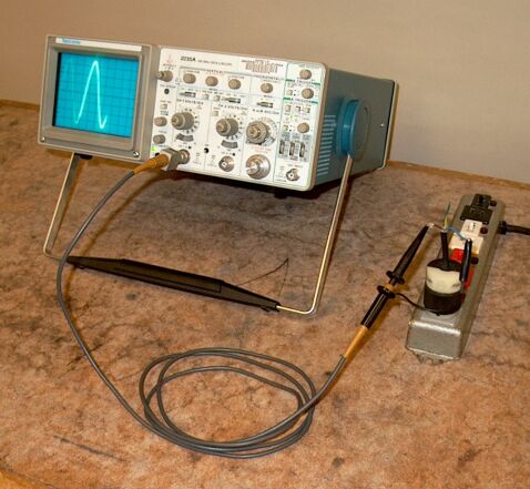
Placing one of the inputs of an oscilloscope across the AC line allows you to display the 120 VAC waveform.

Placing one of the inputs of an oscilloscope across the AC line allows you to display the 120 VAC waveform.
The voltage across the AC line is roughly sinusoidal, with its extrema centered about zero; hence the designation “AC,” which stands for alternating current. The frequency of this sinusoid (in the U.S.) is 60 Hz. Using AC instead of DC (for direct current) allows power companies to use transformers to increase the voltage at the generator from a few tens of kilovolts, typically, to several hundred kilovolts, often 500,000 volts, at the main transmission lines, and then to step the voltage down again at substations, then further to step it down at neighborhoods, to deliver electricity at 120 volts to individual houses. (See demonstration 72.45 -- Transformer coils.) Even if the average household drew only a nominal current at 120 volts, the total current for a whole city or town, for example, would be huge. When current flows through a transmission line, because of the electrical resistance of the line, some of the work done by the generator in pushing the current through the line, appears as heat, in an amount equal to i2R, where i is the current, and R is the resistance of the line. (See demonstration 64.21 -- Heat coil, 64.24 -- Electric hot dog cooker, or 64.36 -- Light bulbs in series and parallel. Strictly speaking, the units of i2R, which are those of V2/R, are joules/s, or watts, which are those of power.) Providing the current drawn by a city or town, then, at 120 volts, would require impossibly large conductors to lower the resistance of the transmission lines enough that the resistive heating would not melt, or even vaporize, them. Since power is the product of voltage and current (P = iV), if we step up the voltage, we reduce the current by a corresponding factor. To deliver a particular amount of power at 500,000 volts, for example, requires less than 1/4,000 the current we would have to provide at 120 V. For a particular conductor, this means less than (1/4000)2, or less than 6.2 × 10⁻⁸ times the resistive heating losses. This allows for the use of much smaller transmission lines, albeit with somewhat higher resistance than larger ones would have, but still keeping losses from resistive heating to acceptable levels.
When we speak of 120 VAC, we are actually referring to the rms (root-mean-square) voltage of the sinusoid coming from the wall outlet. For a sinusoid, this voltage is 0.707Vp, where Vp is the peak voltage. If we apply a sinusoidal voltage across a purely resistive load, the rms current is 0.707ip, where ip is the peak current. These effective values correspond to the DC values that would give the same power dissipation in the resistor. These are slightly different from the average voltage and current, which are 0.639Vp and 0.639ip for a sinusoid. For AC from the wall, the rms voltage is approximately 120 V, and the average voltage is about 110 V. The peak voltage, then, is actually 120/0.707 = 170 V. This is half the amplitude of the sinusoid. The overall amplitude, which is called the peak-to-peak voltage (Vp-p), is twice the peak voltage, or 340 V.
As noted above, in the United States, the frequency of the AC at the wall outlet is 60 Hz. In Europe and many other parts of the world, the wall voltage is 230 VAC, 50 Hz. Travelers are aware of this, and carry adapters for their electronic devices. Nowadays, most laptop computer supplies can accept multiple voltages at either 50 or 60 Hz. Anyone wishing to use any electrical device that puts a transformer, motor or other inductive element across the line, however, must be careful that the device is rated for operation at a line frequency of 50 Hz. The impedance of an inductor – its inductive reactance – increases linearly with the frequency of the voltage applied to it. (See demonstration 72.63 -- LRC circuit: phase differences, resonance.) If you go to a country where the line frequency is 50 Hz, plug a transformer into the wall to take the line voltage down to 120 V, and then plug into the transformer a device designed for operation at 60 Hz, the roughly 17 percent decrease in line frequency reduces the inductive reactance of the device. This 17-percent reduction in inductive reactance causes a corresponding increase in the current that the device draws. If it is not designed to handle this extra current, the device can be damaged or even destroyed, depending on how it is constructed. (If the transformer itself is not designed to handle the extra current, it, too could be damaged.)
The International Electrotechnical Commission (IEC) has a very nice web page that shows the line voltage and frequency for 216 countries around the world, with diagrams of the electrical plug types used there. You can find that page here.
References:
1) Howard V. Malmstadt, Christie G. Enke and Stanley R. Crouch. Electronics and Instrumentation for Scientists (Menlo Park, California: The Benjamin/Cummings Publishing Company, Inc., 1981), pp. 31-32.
2) Halliday, David and Resnick, Robert. Physics, Part Two, Third Edition (New York: John Wiley and Sons, 1977), p. 861.