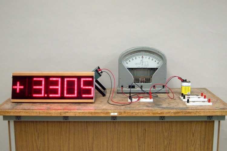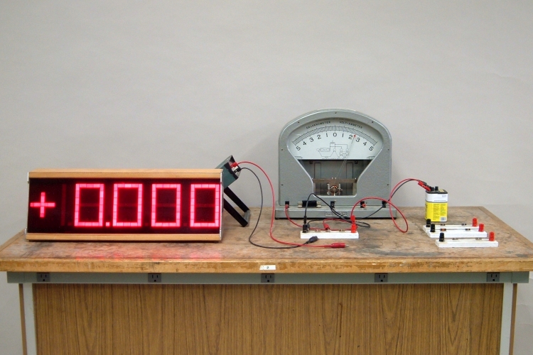
Shown above are a 6-V lantern battery and four voltage dividers, each comprising a pair of resistors of equal value connected in series. The dividers are pairs of 100-Ω, 1-kΩ, 10-kΩ and 10-MΩ resistors. Also in the photograph are a digital multimeter (DMM) with large display (at left), and a galvanometer that has a series resistor connected, of the appropriate value to give a full-scale reading of 5 volts (at right). By connecting the battery across each of the voltage dividers, and then making measurements with the DMM and galvanometer in turn, you can show that the lower impedance of the galvanometer can greatly affect the accuracy of its measurements.
The photograph above shows the pair of 1-kΩ resistors, with the battery connected across the pair, and the DMM reading the voltage across the lower half of the divider. The open-circuit voltage across the battery is about 6.5 V, and the 3.3-V reading of the DMM is roughly half of this, as it should be. The photograph below shows the same divider, with the battery connected across it, and the galvanometer reading the voltage across the lower half.
We see that the reading on the galvanometer is about 2.4 volts, significantly lower than the 3.3-V reading obtained with the DMM.
To diagnose a problem with an electrical circuit, or to verify its proper operation, it is often useful to make voltage measurements, either across individual components in the circuit, or between various points in the circuit and some reference, usually the common connection to the negative terminal of the power supply (or battery), usually referred to as “ground.” To do this, one uses an instrument called a voltmeter. The working element in the readout of an analog voltmeter is a d’Arsonval, or moving coil, movement. A coil is suspended on a pivot between the poles of a permanent magnet, so that when a current flows through the coil, the coil experiences a torque about the pivot. The coil has attached to it an indicating needle, and one or two hairsprings (spiral-shaped springs). The hairsprings balance the electromagnetic torque so that the deflection of the needle is proportional to the current flowing through the coil, and they return the needle to its zero position when the current stops flowing. (See demonstration 68.48 -- Torque on current-carrying loop.) The meter is designed so that a particular current gives the needle a full-scale deflection. A scale marked in divisions of that full-scale current allows direct reading of whatever the meter is measuring. To use such a meter as a voltmeter, one inserts a series resistor of the appropriate size to give a full-scale reading for a particular maximum voltage. In this arrangement, Vfs = Ifs(Rmeter + Rseries), where “fs” stands for “full-scale,” and Ifs = Vfs/(Rmeter + Rseries). The current, and thus the scale reading, is proportional to the voltage applied across the meter and series resistor. One can also use the meter as an ammeter (current meter), by placing a shunt resistor of the appropriate size across it, forming a current divider. In this case, a predetermined portion of the measured current flows through the meter, and the rest flows through the shunt resistor. So Imeter/Itotal = [Rshunt/(Rmeter + Rshunt)] One chooses a shunt for which, for a particular maximum current, the portion flowing through the meter gives a full-scale reading. The galvanometer shown above comes with a set of series resistors so that it can be used as a voltmeter, with a choice of voltage ranges, and a set of shunts, so that one can use it as an ammeter, with a choice of current ranges. Though single-function meters such as voltmeters or ammeters exist, most meters are built into devices that have the necessary resistors, batteries and switches, so that with the appropriate switch setting, one can measure voltage, current or resistance. These are known as volt-ohm-milliammeters (VOMs), or multimeters.
Whenever you measure the voltage between two points in a circuit, the voltmeter becomes a part of the circuit. If the meter draws very little current compared to the current flowing in the part of the circuit across which you are measuring, then connecting the meter introduces a negligible change in the current flowing in the circuit, and thus a negligible change in the voltage across that part of the circuit. The voltage you measure is thus close to the voltage that would obtain without the meter there. For this situation to hold, the resistance, or input impedance, of the meter must be much greater than the resistance of the part of the circuit across which you are trying to measure the voltage. (See demonstration 64.09 -- Ohm’s law.) The galvanometer shown above, with the appropriate series resistor to yield a full-scale reading of ±5 volts, has a resistance of about 1 kilohm. The DMM on its DC V setting, has a resistance of 10 megohms. The battery voltage is just over 6.5 V, so the midpoint of each voltage divider with the battery across it, should be at about 3.25 volts with respect to the negative terminal of the battery. (Vmidpoint = Vbattery × R/(R + R) = (1/2) Vbattery. Since the resistors in each pair are not identical, the voltage should be close to half the battery voltage, but may not be exactly so.) For the divider shown above, the 10-MΩ resistance of the DMM is 10,000 times greater than the 1-kΩ resistance of the resistors in the divider, and when it is connected across the lower half of the divider it reads 3.3 V. The 1-kΩ resistance of the galvanometer, on the other hand, is equal to that of the resistors in the divider. Placing the galvanometer across the lower half of the divider, then, halves the resistance of that part of the divider ((1/1000) + (1/1000) = (1/500)). See demonstration 64.39 -- Resistors in series and parallel.) The divider becomes a 1-kilohm resistor in series with a 500-ohm resistor, and the voltage across the lower half becomes 6.5 V × 500 Ω/(500 + 1000) Ω = 2.2 V. Hence the reading of 2.4 volts on the galvanometer, which is close to this.
If you try the pair of 100-ohm resistors, you find that the galvanometer reading is much closer to what it should be, since the resistance of the galvanometer is now 10 times that of the resistor, so the resistance of that part of the divider ends up being about 91 ohms ((1/1000) + (1/100) = (1/91)) instead of 100 ohms, closer than the difference that we observed for the pair of 1-k resistors. 6.5 V × 91 Ω/(91 + 100) Ω = 3.1 V. The DMM, of course, gives a reading that is even closer to the actual value.
For the pair of 10-k resistors, the error in the galvanometer reading is even larger than for the 100-Ω and the 1-k pairs. Since the 10-MΩ resistance of the DMM is still 1,000 times larger than that of the 10-k resistors, its reading is still quite accurate. For the pair of 10-MΩ resistors, however, the resistance of the DMM is now equal to that of the resistors in the pair, and it exhibits a similar error to that of the galvanometer connected to the pair of 1-k resistors. The galvanometer connected to the pair of 10-MΩ resistors does not read at all. (It should read about 3.2 mV.)
For an analog voltmeter, the resistance depends on the current sensitivity of the meter, that is, how much current is necessary to yield a full-scale reading of the meter. For the galvanometer in this demonstration, a full-scale reading corresponds to a current of 5 mA, so for a full-scale reading of 5 V, its resistance (Rmeter + Rseries) is 5 V/5 mA = 1,000 Ω. This resistance is normally quoted as its ratio to the full-scale voltage. The galvanometer in this demonstration thus has a resistance rating of 1,000 Ω/5 V = 200 ohms per volt. The meter in a typical analogue voltmeter has a current sensitivity of several tens of microamperes, to give a resistance rating of tens of thousands of ohms per volt. For example, a Simpson model 260 multimeter set to measure DC volts has a resistance of 20,000 ohms per volt. A Micronta “range doubler” multimeter (catalogue no. 22-204U) on the DC volts setting has a resistance of 25,000 ohms per volt, and on the (V-A)/2 setting (full-scale voltage half that on the DC V setting), it has a resistance of 50,000 ohms per volt. For general purposes, such resistances are high enough that the errors in the meter readings are not significant. When the resistances in the circuit being measured are not much less than that of the meter, though, as this demonstration shows, the meter readings can exhibit significant error. In such cases, unless the circuit resistances are greater than a few megohms, a DMM can give accurate measurements.
It is possible to increase the resistance of an analog meter by putting a high impedance circuit between it and the points where the voltage is to be measured. Until the advent of DMMs, if one needed high meter resistance, one used an instrument called an FET VOM. This is a meter that has on its input a circuit that uses a field-effect transistor (FET), which provides a very high resistance between the input and the rest of the circuit. (This type of circuit is similar to what is on the input of a DMM.) Before the advent of semiconductors, one used a VTVM – a vacuum tube voltmeter (or VTVOM, a vacuum tube volt-ohm-milliameter). Both of these types of meter offer input resistance similar to that of a DMM.
References:
1) Howard V. Malmstadt, Christie G. Enke and Stanley R. Crouch. Electronics and Instrumentation for Scientists (Menlo Park, California: The Benjamin/Cummings Publishing Company, Inc., 1981), p. 20.
