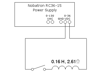
A large coil is connected in series with a tap switch and a DC power supply. This 1000-turn coil has an inductance of 0.16 henries and a DC resistance of 2.61 Ω. With the power supply set for maximum output, when you depress the switch, a current of approximately 16.5 amperes flows through the coil. The voltage across the coil is about 43 volts. The current flowing through the coil creates a large magnetic field, which causes the dip needle (on top of the power supply) to deflect strongly towards the coil. When you release the tap switch, the collapsing magnetic field induces a large reverse current into the coil, and the released energy appears as an arc in the gap of the tap switch. Inserting the large metal rod into the coil increases the strength of the magnetic field, so that when you press the tap switch, the dip needle deflects even more vigorously, and when you release the tap switch, the arc is noticeably more intense. While this circuit is quite simple, an overhead transparency of the schematic for it is available for you to display in class, or you may download a .pdf version here to show on the data projector. The schematic is below:
This demonstration illustrates the storage of energy in a magnetic field, and its subsequent release when the current that produces the magnetic field stops. If we consider a series RL circuit, the relationship between the voltage across the circuit and the current through it is:
If we multiply each side by i, this gives the rate at which the power supply delivers energy to the circuit, or the power dissipated in the circuit:
Some of this energy shows up as heating of the resistor, which is given by the i2R term on the right. The rest is stored in the magnetic field. The second term on the right gives the rate at which energy is stored in the magnetic field, which we can write as dUB/dt. Equating this to the right-hand term and then integrating gives the magnetic energy stored in a coil with inductance L and carrying a current i as UB = (1/2)Li2.
Taking the current of 16.5 amperes and the inductance of 0.16 henries, we calculate the energy stored in the magnetic field as (1/2)(0.16H)(16.5A)2 = 22 joules. The L/R time constant for this coil is 0.16 H/2.61 Ω, or 61 ms. (See demonstration 72.57 -- LR circuit rise time, which also contains a short note about inductance.) This means that within less than 1/3 second after you close the switch, the current through the coil will have reached 99% of its maximum. When you open the switch, this energy is released in the form of an arc across the switch.
Inserting the iron rod increases the magnetic field and, thus, the effective inductance and the total energy stored in the magnetic field, so that when you insert the rod into the magnet and then perform the demonstration, the dip needle deflects more vigorously than before, and the spark is significantly more intense than before, as noted above.
The energy stored in the magnetic field of an inductor can cause damage in circuits that switch the current through an inductor on and off. For instance, if one uses a transistor to switch the current through an inductor, the collapsing magnetic field when the transistor switches off puts a forward bias on the transistor junction that is connected to the coil, and could drive a large enough current through it to do damage, either to the transistor itself or to other components connected to it. The arcing that occurs in mechanical switches that apply current to inductors can damage the switch contacts and greatly shorten the life of the switch. To prevent this, one places a large diode across the coil to provide a path for the reverse current that results from the field collapse. One can also use a series resistor/capacitor combination, called a “snubber” network, placed either across the inductor or across the switch, to absorb the energy released when the switch opens.
References:
1) Halliday, David and Resnick, Robert. Physics, Part Two, Third Edition (New York: John Wiley and Sons, 1977), pp. 801-802.
2) Horowitz, Paul and Hill, Winfield. The Art of Electronics (New York: Cambridge University Press, 1989), pp. 52-53.