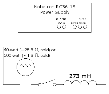
A DC power supply, large coil, knife switch and light bulb are connected in series. With the power supply on, close the knife switch. The small (40-watt) bulb, with higher resistance, lights instantly, whereas the large (500-watt) bulb, with lower resistance, takes a couple of seconds to light. A schematic of this circuit is below:
While this circuit is quite simple, an overhead transparency of the schematic for it is available for you to display in class, or you may download a .pdf version here to show on the data projector.
Several demonstrations in this chapter use two coils to show mutual induction, the induction by changing magnetic flux set up by one coil, of an emf in a second coil. This demonstration shows a manifestation of self-induction – the induction of an emf in the same coil that is making the changing magnetic flux. This emf is called a self-induced emf. It is determined by Faraday’s Law, which states that E = -d(NΦB)/dt, where N is the number of turns in the coil. NΦB is the number of flux linkages in the coil. If the coil does not have an iron core, and it is not near any magnetic materials, NΦB is proportional to the current, i, through the coil, or NΦB = Li. The proportionality constant, L, is called the inductance of the coil. Faraday’s Law gives E = -d(NΦB)/dt = -L(di/dt). We can rewrite this as L = -E/(di/dt), from which we can see that the unit of inductance is the volt-second/ampere. The name for this unit is the henry, which is abbreviated as H.
If we rearrange the second equation above as L = NΦB/i, and then imagine a section of length l near the center of a long solenoid, we can obtain the inductance in terms of the geometrical properties of the coil. For such a section, the number of flux linkages is NΦB = (nl)(BA), where n is the number of turns per unit length, B is the magnetic field inside the solenoid, and A is the cross-sectional area of the solenoid. From Ampère’s law (by integrating around a rectangular path enclosing several turns of an ideal solenoid) we have B = μ0ni, which gives NΦB = μ0n2liA. So L = NΦB/i = μ0n2lA. Since n = N/l, L = μ0N2A/l. (μ0, the permeability constant, equals 4π × 10-7 tesla·meter/ampere, or 1.26 × 10⁻⁶ H/m. 1 tesla equals 1 N/(A·m), so 1 T·m/A = 1 N·m/A2·m = 1 N/A2. 1 H = 1 V·s/A = 1 N·m·s/(C·A) = 1 N·m/A2. So 1 H/m = 1 N/A2 = 1 T·m/A.)
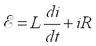
In the circuit above, if the coil were not present, the current through the lamp, which is an almost completely resistive load, would immediately rise to its maximum value of E/R when you closed the switch. With the coil in the circuit, though, as soon as current starts to flow, the self-induction in the coil produces an emf across the coil. By Lenz’s Law (see demonstration 72.09 -- Lenz’s law), and as Faraday’s law above implies, this emf opposes the potential placed across the coil by the power supply and, thus, the rise of current through the circuit. The lamp thus experiences the sum of two opposing emfs, a constant one from the power supply, and an opposite, time-dependent one equal to -L di/dt from the self induction of the coil. Over time, the current increases more slowly, which causes the emf from self-induction in the coil to decrease, and the current in the circuit approaches E/R asymptotically.
To find an expression for the current in the circuit, we note that the sum of the voltages across the resistor and the inductor equals the voltage applied by the power supply, or:
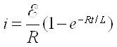
The solution to this differential equation is:
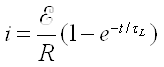
which we can also write as:
where τL, the inductive time constant, equals L/R. This is the time it takes for the current to reach 63% of its maximum value. (At t = L/R, the term in parentheses equals 1 - e-1, or 1 - 0.37 = 0.63.) For a graphical display of the behavior of such a circuit, see demonstration 72.60 -- LR circuit to oscilloscope. R in this circuit, of course, changes as the lamp heats up. (At 120 V, so with normal operating current, the resistances are about 360 Ω and 29 Ω for the 40-watt and 500-watt lamps, respectively.) Still, we can estimate the L/R time constants for the lamps when they are cold. They are about 0.273 H/28.5 Ω = 9.58 ms, and 0.273 H/1.6 Ω = 170 ms, for the 40-watt and 500-watt lamps, respectively. These differ by a factor of about 18. With these values for R, we calculate that for the current to reach 90% of its maximum it takes about 22 ms for the 40-watt lamp, and about 390 ms for the 500-watt lamp. This difference is quite noticeable when you change from one lamp to the other and then close the switch.
References:
1) Halliday, David and Resnick, Robert. Physics, Part Two, Third Edition (New York: John Wiley and Sons, 1977), pp. 720, 757, 795-9.