 |
 |
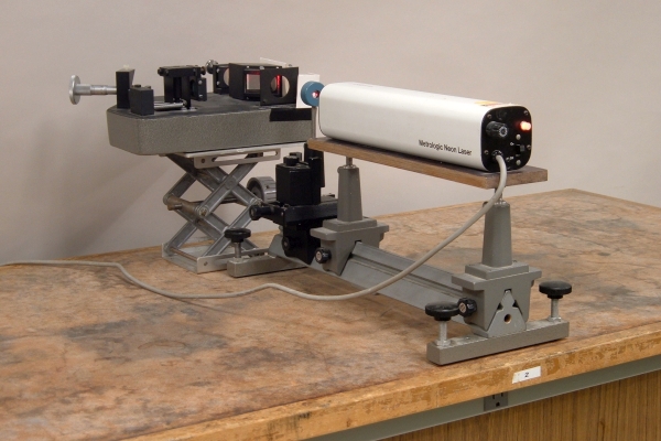
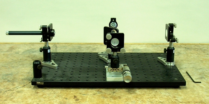
The UCSB physics department now has two Michelson interferometers. One is an R.J. Beck interferometer, shown in the photograph above. This instrument has a compensator between the beam splitter and fixed mirror, and a 5:1 reduction on the micrometer head that adjusts the length of the variable arm, which produces a mirror movement of two microns for the smallest division on the micrometer scale. The second is a home-built unit, shown below. The new instrument boasts a gothic-arch-bearing 40-mm translation stage with a differential micrometer whose smallest division corresponds to a movement of one micron, and a modular construction that allows great flexibility in setting up the interferometer. You can find some photographs and explanations of some of the activities we have done with the new interferometer, and others that we have planned, here, in a web page written by James Hogg (a UCSB graduate student in physics, who has since finished his Ph.D.).
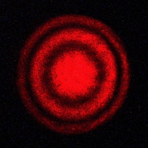
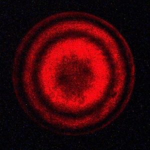
The R.J. Beck instrument is shown above with a Metrologic ML820 laser, which emits light whose wavelength is 632.8 nanometers. The optic in the blue mount in front of the laser is a beam expander, which spreads the beam over most of the mirror area. Half of the input light is reflected by a beam splitter to the moveable mirror (to the right of the micrometer assembly) to make the “variable arm,” and half goes through to the fixed mirror (at the rear, on the right) to make the “fixed arm.” The mirrors reflect the light back to the beamsplitter, where the portions of the beams that are reflected and transmitted towards the exit aperture (on the right, 90 degrees to the input aperture) recombine. If the path lengths of the two arms differ by exactly an integral number of wavelengths of the light, the two beams undergo constructive interference, giving an intensity maximum. If the path lengths differ by exactly an integral number of wavelengths plus (or minus) a half wavelength, they undergo destructive interference to give an intensity minimum. One thus observes a pattern of fringes that appears to move as one adjusts the length of the variable arm. When the two mirrors are “coplanar,” that is, they are exactly perpendicular to the beam paths, one observes a symmetrical pattern such as those shown below.
The image on the left shows an interference maximum at the center, and the image at right shows an interference minimum at the center. In each photo you can see two fringes (and perhaps part of the next) surrounding the center spot. When the two arms are exactly the same length (i.e., they differ by exactly zero wavelengths!) and the mirrors are coplanar, the central maximum grows to fill the entire field.
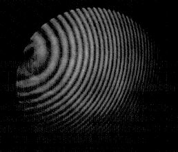
When the mirrors are not coplanar, one can obtain so-called “hyperbolic” fringes, which appear as straight vertical lines. The fringes in the photograph at the top of this page indicate a mirror alignment somewhere between that which would give circular fringes and that which would give hyperbolic fringes.
