|
 |
A beam of electrons focused on a crystal mounted inside the cathode ray tube produces the diffraction pattern shown above.
Inside the apparatus in the photograph at left, is a special cathode ray tube that has a set of samples mounted between the electron gun and the front face of the tube. These are two-dimensional hexagonal pyrolytic graphite, polycrystaline hexagonal pyrolytic graphite, polycrystaline aluminum and thin film aluminum (though it is hard to tell a difference between the two types of aluminum). On the front panel are controls by which you can aim the electron beam at any of these samples to obtain a diffraction pattern. First, set the electron energy to 7 kV via the large knob at right. (The meter above the knob reads the energy in kV.) Then use the vertical and horizontal controls to aim the beam. Adjust the intensity (not too high!) and focus as needed.
When a beam of light passes through a row of slits, or is reflected by a row of grooves, it undergoes diffraction and inteference to form a pattern of alternating bright and dark spots – a diffraction pattern. (See demonstrations 84.06 -- Laser beam diffracted through various slits, and 84.18 -- Laser beam diffracted by reflection gratings.) This is most noticeable when the dimensions and spacings of the slits or grooves approach the order of the wavelength of the light passing through or being reflected by them. In crystalline solids, the atoms (or groups of atoms) form a lattice in which the planes on which they lie exhibit a regular spacing along one or more axes. (See demonstration 88.27 -- Crystal models.) This spacing is typically on the order of ångstroms, which corresponds to the wavelength of light in the x-ray region of the electromagnetic spectrum. If one passes a beam of x rays through a crystalline solid, as they interact with the atoms in the crystal lattice they undergo diffraction and interference, and they form a diffraction pattern. From the locations and intensities of the various spots in the diffraction pattern, one can calculate the spacings of the planes along which the atoms lie, and thus figure out how the atoms are arranged in the crystal. This technique is called x-ray crystallography, and since the early part of the 20th century it has been used with great success to determine molecular structures.
As noted above, the apparatus used in this demonstration does not send a beam of x rays toward the samples mounted inside it, but rather, it aims a beam of electrons at them. Whereas x rays are electromagnetic radiation – waves – electrons are particles. Normally, we associate diffraction and interference with waves, but not with particles. For a long time, physicists debated whether light was a wave or a particle. By the 19th century, its wave-like properties were well established. At around the turn of the 20th century, some observations indicated that light might perhaps also behave as particles do. With the confirmation of the photelectric effect in 1914 by Milliken (see demonstration 88.09 -- Photoelectric effect), and of the Compton effect in 1923, it became evident that light could also behave as a particle. (In 1926, G. N. Lewis coined the word photon for one of the discrete packets in which light delivers its energy.) Intrigued by this property of light, Louis de Broglie imagined that perhaps particles could also exhibit wave-like properties. In his doctoral thesis, which he presented to the Faculty of Science at the University of Paris in 1924, he proposed that just as for electromagnetic radiation the energy is related to the frequency of the wave associated with its motion by E = hν, so is the energy of a particle related to the frequency of the wave associated with its motion. In this equation, E is (kinetic) energy, h is Planck’s constant (= 6.626 × 10⁻³⁴ J·s) and ν is frequency (in Hz). For a photon, ν = c/λ, where c is the speed of light, and λ is wavelength. Thus, for a photon, E = hc/λ. Momentum, p, for a photon equals E/c, which gives p = h/λ. If we rearrange this, we obtain the de Broglie relation:
λ = h/p
For this work, de Broglie was awarded the Nobel prize in physics in 1929. You can read his Nobel lecture here. The de Broglie relation holds for particles as well as waves. In 1926, Elsasser suggested that this could be verified in the same way in which people studied the wave-like behavior of x rays, that is, to aim a beam of electrons at the surface of a crystalline solid and look for a diffraction pattern. Davisson and Germer in the United States, and G. P. Thomson in Scotland, performed such experiments and confirmed that just as one could do with x-rays, one could obtain a diffraction pattern from a crystalline solid with electrons. (They looked at diffraction of a beam reflected from the surface, whereas in this demonstration we observe the diffraction of the beam transmitted through the crystal.) For this work, Davisson and Thomson were awared a Nobel prize. (G. P. Thomson was the son of J. J. Thomson, who discovered the electron by means of an experiment that demonstrated its behavior as a particle. For this and related work, J. J. Thomson was awarded a Nobel prize.)
For a particle, p = mv, and the kinetic energy, K (for v ≪ c; vide infra), equals (1/2)mv2. Thus, p = √(2mK), and we have for the wavelength:
λ = h/√(2mK)
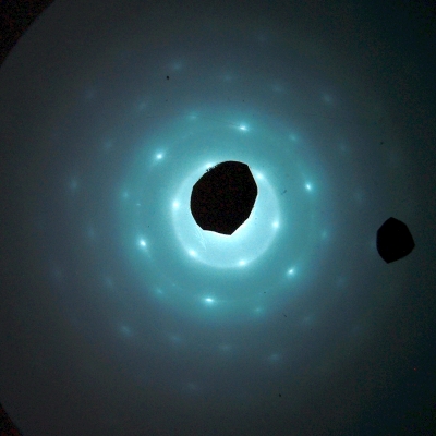
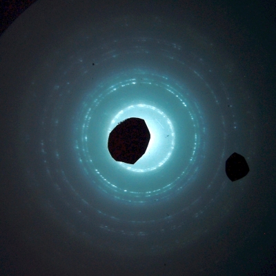
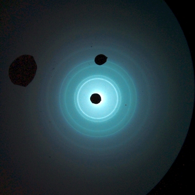
The mass of an electron is 9.109 × 10⁻³¹ kg, and at 7,000 volts its energy is (7,000 J/C)(1.602 × 10-19 C) = 1.121 × 10⁻¹⁵ J. Substituting these values and that of Planck’s constant into the equation above gives a wavelength of 0.1466 Å, which is similar in magnitude to the spacing among the atoms in a solid, which, as noted above, is on the order of ångstroms. Thus, when we aim a beam of 7,000-V electrons at one of the sample targets in the apparatus, we obtain a diffraction pattern like one of those shown below.
2-D hexagonal pyrolytic graphite
Polycrystalline hexagonal pyrolytic graphite
Thin film aluminum
If we rearrange the expression for kinetic energy, we calculate v as √(2K/m), which equals 4.961 × 10⁷ m/s, which is about 16% the speed of light. The relativistic mass is given by the Lorentz equation m = m0/√[1 - (v2/c2)]. The factor 1/√[1 - (v2/c2)] is denoted γ. If we insert the velocity calculated above and the speed of light, we find that γ = 1.014. This means that m, the mass of the electron while it is moving at 4.961 × 10⁷ m/s, is about 1.4% greater than its rest mass. If we make the relativistic correction to the kinetic energy, we find that the actual kinetic energy of the electron is about 1.144 × 10⁻¹⁵ J, which is about 2.1% higher than the 1.121 × 10⁻¹⁵ J calculated above. (See http://hyperphysics.phy-astr.gsu.edu/hbase/Relativ/releng.html#c5, the panel below and links therein, and also http://hyperphysics.phy-astr.gsu.edu/hbase/Relativ/releng.html#c1, the panel below it and links therein.) As v increases, this error becomes larger, and as v approaches c it becomes great enough that one must make the relativistic correction. For the purposes of the experiments that one performs with this apparatus, the 2.1 % error in the kinetic energy is small enough that this is not necessary.
References:
1) Robert Eisberg (A UCSB professor emeritus!) and Robert Resnick. Quantum Physics of Atoms, Molecules, Solids, Nuclei and Particles (New York: John Wiley and Sons, 1974), pp.63-70.
2) Halliday, David and Resnick, Robert. Physics, Part Two, Third Edition (New York: John Wiley and Sons, 1977), pp. 1117-20.
3) http://hyperphysics.phy-astr.gsu.edu/hbase/debrog.html#c1, the panels below and links therein.