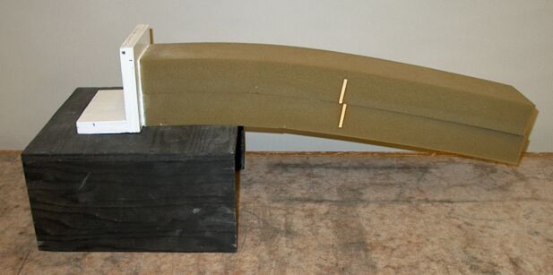
When the free end of the logs is supported by the jack (at the same height as the fixed end), the logs are straight, and the white line on each log is aligned with the line on the other log. If you remove the jack, gravity pulls the free ends down. This results in shear within and between the logs, which causes the white lines to shift apart as shown in the photograph above.
A force applied parallel to the plane of cross section of a material, or to the plane of the interface between two pieces of a material (or such planes within a material) is called a shear force. A force that when applied to an object could deform it is called a stress. If it is parallel to the plane of cross section, it is a shear stress. This bears comparison to a normal stress such as that illustrated in demonstration 32.21 -- Stretch wire to breaking point, which is perpendicular to the cross section of the material (and in this case is a tensile stress). The foam logs above represent a beam that is supported horizontally at one end and free at the other end, to form a cantilever. Gravity acts parallel to the vertical cross section of the foam logs, which constitutes a shear force acting along their length and causing them to bend downward from the fixed end. This bending generates a shear force along the surface at which the logs make contact over their length. The diagram below shows how this might look if the two logs were glued together along that surface (or they were one piece).
We see that the material at the top of the cantilever is being stretched; it is under tension. The material at the bottom of the cantilever is being squeezed; it is under compression. The material along the middle of the cantilever, where the dashed line runs, is being neither stretched nor compressed. This surface is called the neutral surface. Above this surface, the material is under tension, and below it, the material is under compression. These tensile and compressive stresses are proportional to the distance from the neutral surface. These forces act along planes within the material, parallel to the planes of the top and bottom surfaces, and are thus shear forces. If the layers within the cantilever did not deform (stretch or compress) under these shear stresses, they should slide over each other. As noted above, if the two foam logs were one piece, when supported only at the left end, they should resemble the drawing above. Since they are separate pieces, when they bend, they slide over each other. The friction between them is not great enough for the top log to compress the bottom log and for the bottom log to stretch the top log. Each log itself resembles the drawing. From the middle up, the log is stretched, the greatest deformation, or strain, occurring at the top surface, and from the middle down, the log is compressed, the greatest deformation occurring at the bottom surface. This causes a rotation of the vertical planes along each log, as shown by the white lines near the middle of the logs, and by the ends of the logs, which are no longer vertical, but are now rotated in the clockwise direction. The top surface of the bottom log, which is now under tension, extends past the bottom surface of the top log, which is now under compression.
When the logs are straight (and horizontal), the white lines on them are aligned (and vertical). If the two logs were glued along the middle surfaces, the plane along which they meet would become the neutral surface, and when they bent, the top log would be stretched and the bottom log would be compressed as described above. The two white lines would rotate as one line, about the point where they intersect the two surfaces. Since the logs can slide over each other, the white line on each log rotates, and the two lines are displaced from each other as shown in the photograph.
A more detailed description of the action of shear forces in a cantilever is given on the page for demonstration 32.30 -- Bending boards.
