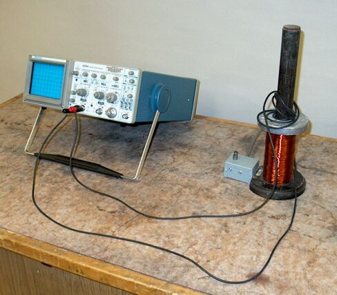
Loop the wire once around the core extending from the Elihu Thomson coil, and press the switch. The oscilloscope displays a sinusoid. As you increase the number of turns you loop around the core, the amplitude of the sinusoid increases.
The Elihu Thomson coil, shown above, is a solenoid wound around a core that is a bundle of thin iron rods and extends some distance above the top of the solenoid. The momentary-contact switch attached to the base of the coil places the ends of the coil across the AC line. This causes an AC current to flow in the coil, which sets up an oscillating magnetic field in the core. (See, for example, demonstrations 68.46 -- Magnetic fields of coils, and 68.13 -- Right-hand rule model.)
As noted in the pages for demonstration 72.03 -- EMF induced by moving magnet, and 72.06 -- EMF induced by moving conductor, a changing magnetic flux in a loop of wire induces an electromotive force (emf) in the loop. This is Faraday’s law, ∮E·dl = -dΦB/dt, or E = -dΦB/dt. For a coil in which the turns are closely spaced, the flux through each turn is the same, and an emf appears across each turn. If the coil has N turns, then, the emf across the whole coil is E = -NdΦB/dt. If you wrap one loop of the black wire around the core of the Elihu Thomson coil and press the switch, the oscilloscope displays a sinusoid with magnitude E. If you wrap a second loop around the core, the amplitude of the sinusoid rises to 2E, for three loops it is 3E, etc. For N loops that you wind around the core, the amplitude should be NE.
Because the wire itself forms a loop, just setting it over the core without completing a turn produces an EMF. Because of this, depending on how the wire is oriented when you wrap the first full loop around the core, the amplitude of the sinusoid you observe may be anywhere from about 650 mV to 1 volt (peak-to-peak). Each additional loop adds about 0.5 volts to the amplitude.
This demonstration illustrates the phenomenon of mutual induction, the linking of two coils by the magnetic flux produced by a current in one of the coils. If we call the Elihu Thomson coil coil 1, we can define the mutual inductance of coil 2 (however many loops of wire you wrap around the Elihu Thomson coil) as M21 = N2Φ21/i1, or M21i1 = N2Φ21. If i varies with time, then M21di1/dt = N2dΦ21/dt. The right side of this is the emf in Faraday’s law, above, without the minus sign, so we have E2 = -M21di1/dt. If we were to connect the Elihu Thomson coil to the oscilloscope (on a much more sensitive scale), and apply an oscillating voltage across the turns of wire we have looped around the coil, we should find E1 = -M12di2/dt. It turns out that M12 = M21, and we can drop the subscripts and call the mutual inductance M. The SI unit for M is the henry, which equals 1 V·s/A, or 1 weber/A. The value of M, and how one calculates it, depend on the geometry of the coils and their orientation with respect to each other.
References:
1) Halliday, David and Resnick, Robert. Physics, Part Two, Third Edition (New York: John Wiley and Sons, 1978), pp.720, 770-4, 805-6, 886.