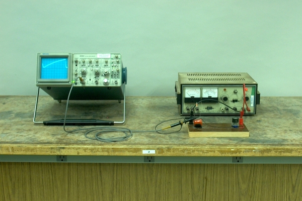
The circuit in this demonstration comprises a variable resistor and capacitor, in series, with a neon lamp placed in parallel with the capacitor. The free end of the variable resistor (in this case, the wiper), is connected to the positive terminal of the power supply, and the opposite end of the capacitor and neon lamp are connected to the negative terminal. The oscilloscope monitors the voltage across the capacitor and the neon lamp. It is called a pacemaker circuit, because the early pacemakers used this type of oscillator to stimulate the heart. Instead of a neon lamp, however, they used a four-layer semiconductor device called a silicon-controlled rectifier, or SCR, to discharge the capacitor. This type of oscillator is known as a relaxation oscillator. A schematic of this circuit is below.
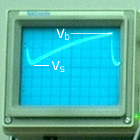
The power supply, the connections to which are labeled “+” and “-”, is set at 100 volts. Initially, the resistance of the neon lamp is very high, so the capacitor charges through the resistor. When the potential across the capacitor reaches the breakdown voltage of the lamp (Vb), the lamp fires, at which point its resistance drops dramatically. The capacitor quickly discharges through the lamp. When the voltage across the capacitor drops to just below the voltage necessary to sustain the discharge in the lamp (Vs), the lamp goes out, and its resistance again becomes very large. The capacitor then begins to charge again, and the cycle repeats. The resulting waveform is a sawtooth, one cyle of which is shown below.
From the analysis given in demonstrations 64.51 — RC circuit to galvanometer(s) and 64.54 — RC circuit to oscilloscope, we find that the voltage across the capacitor, V, equals Va(1-e-t/RC), where Va is the voltage applied across the circuit. If we call the time for the capacitor to charge to the lamp sustaining voltage, Vs, T1, and the time for the capacitor to charge to the lamp breakdown voltage, Vb, T2, we have
Vs = Va(1-e-T1/RC), and Vb = Va(1-e-T2/RC),
which we can rearrange to give Vae-T1/RC = Va - Vs, and Vae-T2/RC = Va - Vb. Dividing one equation by the other gives
e(T2 - T1)/RC = (Va - Vs)/(Va - Vb).
Taking the logarithm of both sides gives (T2 - T1)/RC = ln [(Va - Vs)/(Va - Vb)]. If we call the period (T2 - T1) τ, then
τ = RC ln [(Va - Vs)/(Va - Vb)],
and the frequency of oscillation, ν, equals 1/τ =1/{RC ln [(Va - Vs)/(Va - Vb)]} Here we are ignoring the discharge time, which at low frequencies is small compared to the period.
The neon lamp in this circuit fires at about 73.8 V, and it goes out below about 57.2 V. With an applied voltage of 100 V, the term
(Va - Vs)/(Va - Vb) equals 42.8/26.2 = 1.63, and ln (1.63) = 0.491.
So for this circuit, τ = 0.503R(1.0 × 10⁻⁶ F), and ν = 1/[0.503R(1.0 × 10-6 F)]. With the variable resistor set at maximum, that is, 1 MΩ, ν is about 2.0 Hz. Reducing R raises the frequency. As you increase Va, (Va - Vs)/(Va - Vb) increases toward 1 (and its natural logarithm decreases toward zero), thus also increasing the frequency. Because the discharge time is not zero, above a certain frequency the shape of the waveform becomes distorted (the sharp corner becomes rounded), and if we continue to raise the frequency, we reach a point where the neon lamp never quenches, but stays on continuously.
Important technical note: Whichever oscilloscope you use, you must use a high-impedance probe (10 MΩ) for the frequency to agree reasonably well with the calculation above. The 2.2-MΩ impedance of the Agilent probe is too close to that of the 1-MΩ variable resistor, and thus increases the charge time and lowers the oscillator frequency. The scope probe acts as the lower leg of a voltage divider, with the variable resistor as the upper leg. The maximum voltage across the capacitor, ignoring lamp breakdown, is 100 V (Rprobe/(Rvariable + Rprobe). When the variable resistor is set at small values relative to the probe impedance, the effect of the probe is small. With the variable resistor set at maximum (1 MΩ), however, and the power supply set at 100 V, a 2.2-MΩ probe drops the voltage across the capacitor to about 69 V (100 (2.2/(3.2))). This is below the breakdown voltage of the lamp, and the lamp never fires. Reducing R below about 0.78 MΩ allows the oscillator to work, but at much lower frequency than corresponds to R = 0.78 MΩ. As you lower R, the effect of the probe becomes less severe. With the 10-MΩ Tektronix probe, the drop is not nearly as great, and the oscillator functions essentially as you would expect.
References:
- 1) Weil, Gerhard; Engl, Walter L. and Renz, Albrecht. IEEE Journal of Solid-State Circuits, SC-5 (2) 1970, 67-73.
- 2) Diefenderfer, A. James. Principles of Electronic Instrumentation, Second Edition (Philadelphia: W.B. Saunders Company, 1979), pp. 205-7.