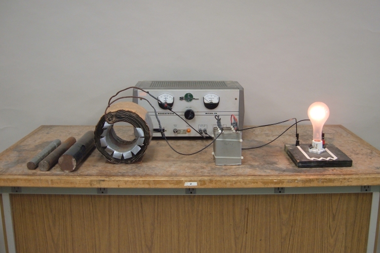

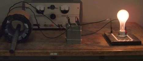
A large coil (0.16 H), a bank of capacitors (40 μF total), a 500-W light bulb, and an AC power supply are connected in series. With the power on, as you slowly insert a large iron rod into the coil, the light bulb brightens and then dims as you bring the circuit into, and then back out of, resonance. At left in the photograph are a large iron rod, a small iron rod and a bundle of small-diameter iron rods.
The page for demonstration 72.63 -- LRC circuit: phase differences, resonance, describes in detail the workings of an LRC circuit – the resonance condition, phase differences between voltage and current in the inductor and in the capacitor, and the resulting voltage phase differences among the inductor, capacitor and resistor, and how the phase differences, and voltage amplitudes, change when the circuit is taken out of resonance in either direction (to higher or lower frequency than the resonant frequency). The circuit for that demonstration comprises small components, all of which fit on a single board for display, and you bring the circuit into and out of resonance by changing the frequency of the function generator that drives it.
The circuit in this demonstration has a very large coil for the inductor (0.16 henries, at left in the photograph), four large 10-microfarad capacitors tied together in parallel to make one 40-microfarad capacitor (in the middle of the photograph), and a 500-watt light bulb for the resistor (at right). The schematic for this circuit is shown below. You can download a .pdf file for display to the class, here.
In this circuit, the voltage source is a variable transformer connected to the AC line, which produces a sinusoidal voltage whose frequency is 60 Hz, which corresponds to an angular frequency of (60 × 2π) 380 radians/s. When the circuit is at resonance, the reactance of the inductor and the reactance of the capacitor are equal. At this point, the voltage across the capacitor lags the input voltage by 90°, and the voltage across the capacitor leads the input voltage by 90°. These voltages are thus 180° out of phase and add to zero, and the voltage across the light bulb equals the applied voltage. The current through the circuit is at its maximum, and the bulb is at its brightest. Resonance occurs when the frequency of the applied voltage equals the inverse square root of the product of the inductive and capacitive reactances, that is, ω = 1/√(LC). For this circuit, then, the resonant frequency is 1/√(0.16 × 40 × 10-6) = 400 radian/s = 63 Hz.
As we can see, the resonant frequency of this cirucit is close to, but slightly greater than, the line frequency. For resonance to occur at the line frequency, the product LC must be slightly larger. The capacitance is fixed, but by inserting an iron rod into the coil, you can increase the inductance. For resonance to occur at 60 Hz, L (= 1/(ω2C)) must be around 0.18 H. As you insert the rod, the inductance increases until it reaches this value, and the bulb becomes brighter as you do so. At some point, further inserting the rod increases the inductance to where it is greater than 0.18 H, and the circuit goes out of resonance in the opposite direction (the line frequency is now too high), causing the bulb to grow dimmer.
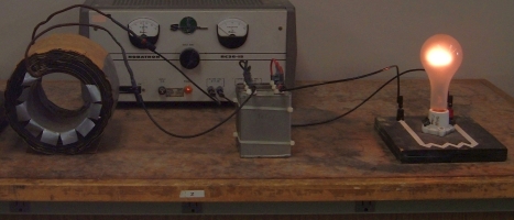
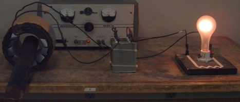
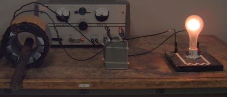
When you introduce an iron core into the coil, energy loss can occur in two ways. One way is by hysteresis, a lag between the change in magnetic flux the core experiences from the coil, and the emf that the core in turn induces in the coil (see demonstration 68.72 -- Hysteresis), which is due to magnetization of the core, and which you can minimize by using soft iron for the core. The second way is through eddy currents induced in the core by the oscillating magnetic field. (See 72.27 -- Eddy current tube, 72.30 -- Eddy current levitation, 72.33 -- Eddy current pendulum, 72.36 -- Eddy current brake, or 72.39 -- Eddy current rotation.) You can reduce these currents by using a laminated core, made up of layers, instead of a solid one, as is usually done in transformer cores. Available for this demonstration, in addition to the iron core shown in the photograph, is a smaller solid core, and also a core made of a bundle of small-diameter iron rods bound together into a cylinder. When you insert this last one, when you reach resonance, the bulb glows significantly more brightly than it does with either of the two solid cores (both of which give similar results), as shown in the photographs below.
 |
||
Off resonance |
||
 |  |
|
At resonance, large rod | At resonance, small rod |
|
 |
||
At resonance, bundle |
||