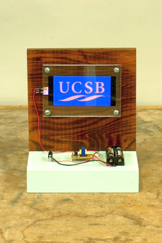

Behind the transparency with the UCSB logo is an electroluminescent display. Turn the switch (at left on the base) on, and the display glows, lighting up the UCSB logo.
Mounted on the base and backboard in the photograph above are a Light Works USA™ power supply and electroluminescent (EL) lamp, made by Miller Engineering. Generally speaking, electroluminescence refers to any process in which a material emits light when a voltage is applied across it. One example is that of injection of charge carriers into a semiconductor junction, as in an LED, which is illustrated in demonstration 64.56 – Light-emitting diode (LED) and demonstration 88.10 – Planck’s constant demonstration. The EL lamp in this demonstration operates via a mechanism commonly called electron impact, or EI, in which electrons that have been accelerated by the application of an electric potential, undergo elastic collisions with a phosphor, thus putting it into an excited electronic state. When the phosphor relaxes from that excited state back to the ground state, it emits a photon. Typical phosphors used in EL lamps contain a ZnS host lattice doped with other transition metals (perhaps most commonly Mn and Cu, but often others), mixed with an organic binder. This phosphor is sandwiched between two thin electrodes, which can be made either of thin layers of glass, or in a flexible display, plastic. The rear electrode can be opaque, and often has a metal coating to make it conductive. Sometimes, to improve the efficiency of the device, this coating is made reflective as well. The front electrode must be transparent, and is typically coated with either a thin layer of indium tin oxide or a conductive polymer. Typically, between the rear electrode and the phosphor layer is a dielectric layer, on which the phosphor layer is deposited, then the front electrode applied.
As you might guess from the physical description of this device, it acts as a capacitor. When you apply a voltage across the lamp, initially, charges flow into (or out of) the two electrodes. Depending on the polarity of the applied voltage, electrons within the phosphor are accelerated toward the electrode and into it, or away from the electrode and into the phosphor. In either case, if the electric field is great enough, then on their way through the phosphor, the electrons can acquire enough energy over the distance of their mean free path, that when they undergo inelastic collisions with some of the metal centers, they excite the metal atoms (or ions, depending on their oxidation state for the particular structure of the phosphor) from their ground state into a higher-energy state, as described above. The metal atoms subsequently relax to their ground state, emitting a photon in the process. The color of the emitted light depends on the metal or metals used and their concentrations. Since the device is quite thin, and the electron paths short, the field must be quite high, but this can be achieved with an applied voltage on the order of 100 V. If we apply a DC voltage, however, once the device charges, the electric field across the phosphor goes to zero, and no current flows. (This can also happen via polarization of the phosphor, which cancels the applied electric field.) If you apply a DC voltage, the lamp flashes when you first apply the voltage, and again when you remove it. The solution is to apply an AC voltage. With each half cycle, the device charges in the opposite direction, and as this happens, electrons are accelerated back and forth within the phosphor. The power supply for our EL lamp, called an inverter, changes the 3 VDC from two AA cells to (sinusoidal) AC that is about 150 V peak to peak at a frequency of about 1.3 kHz. So the peak voltage across the EL lamp is about 75 V.
Their low power consumption, even light emission over their entire surface, and if they are made with plastic electrodes, their flexibility and ability to be cut into virtually any shape, make EL lamps suitable for a variety of applications, including night lights, backlights for LCD displays in watches, clocks and other devices, and advertising displays, among other things. Our EL lamp is designed for use in a variety of scale models, for example lit signage on buildings, or any part of any kind of model that would be illuminated. It can be cut into any shape, and it is flexible, which gives it considerable versatility in such applications.
References:
1) The emission of light by the mechanism described above is known as the “Destriau effect,” after Georges Destriau, who discovered it in 1936. A paper he published with H.F. Ivey, in the December, 1955 issue of Proceedings of the IRE (Institute of Radio Engineers), titled Electroluminescence and Related Topics, gives a very good background on the subject (accessible via any UCSB computer).
2) Kaiser, Walter; Marques, Ricardo Paulino and Correa, Alexander Fernández, Light emission of Electroluminescent Lamps Under Different Operating Conditions, IEEE Transactions on Industry Applications 49(5), 2361, gives a good description of these devices, how they are made, and how they work (accessible via any UCSB computer).
3) You can also find information at various places on the web. The web page of The Edison Tech Center gives a good presentation of the workings of, uses of, and the history of the development of EL lamps. Dupont’s Processing Guide for DuPont Luxprint® Electroluminescent Inks gives a good overview of how EL lamps work, their structure, how they are manufactured, and their uses.